
Wind power plant

a wind power plant and turbine technology, applied in the direction of rotors, greenhouse gas reduction, vessel construction, etc., can solve the problems of not providing electrical energy, not being able to use all the energy of the swept area, and not being able to provide us with a solution, so as to increase the efficiency of the turbine and increase the speed of the wind

Inactive Publication Date: 2003-02-20
SOSONKINA YEVGENIYA
View PDF0 Cites 53 Cited by
  • Summary
  • Abstract
  • Description
  • Claims
  • Application Information

AI Technical Summary

Benefits of technology

[0029] An object of this invention is to provide a wind power plant for generating electrical energy on a big scale, comprising a plurality of turbines, collected under one roof, so that we will not occupy large areas of land, at the same time, increasing the efficiency of turbines by locating them on higher elevations, one above another and using the higher speed of the wind on higher elevations.
[0030] Another object of this invention is to the simplify the design and efficiency of the rotors by using wide blades made of thin sheet metal or another rigid, strong and durable material, like plastic.

Problems solved by technology

But these windmills were designed for fulfilling specific needs on specific sites and could not provide electrical energy for large grid of electrical power because they had too small scale and could not meet necessary standard for electrical power because of constant change of their speed of rotation and absence of means for controlling this speed.
Propellers, used in most power plants, that we can see, for example, in California, cannot provide us with a solution.
Even theoretically they cannot use all the energy of areas swept by propellers because they move in plane perpendicular to the direction of the wind.
The surface of propeller should be curved to face the wind with proper angle, and it is difficult to build a wide propeller blade twisted at the hub.
Also, we cannot build too long blades because it faces too big distractive centrifugal forces in cross section of their twisted blades near the hub.
At the same time, big amount of small size plants consumes too much areas of the land.
They don't have good aesthetic view, are bad for bird population and difficult for maintenance, especially in case of stormy weather or snow.
But this plant cannot have more than six narrow blades of special shape (see column 4, 10), so the output of energy, which depends of surface of the blades, disposed to the direction of the wind, cannot be big.
This plant also doesn't have any control of the rotational speed, any safety measures and means for maintenance, especially, as it proposes to be located at the sea, and will be broken after the first storm, when the wind can be too erratic and very strong.
The friction between the wheels of the carriages and the tracks can be too high and will be changing with every change of the wind because part of the force of the wind, impacting on the blades, pushes the wheels perpendicular to tracks.
Erratic movement of the generators cannot produce standard electric power.
But this energy system does not have any rate control and does not have any means for preventing synchronous speed of the rotors.
The system also uses propeller type rotors with narrow blades and cannot utilize all the energy of the area swept by these propellers.
It does not have any prevention against storm, snow, can harm the bird population, does not have any safety measures for maintenance and overhaul.
This windmill does not have means for controlling the wheel speed.
The blades are secured to disks but have curved surfaces in horizontal and vertical directions and too complicated, heavy and expensive to be implemented on a large scale.
The size of the shield is too big but it cannot cover from the snow or very strong wind more than 180 degrees of the surface of the rotor from the left side of axis of rotation, if the wind will change the directions too quickly.
At the same time, the air, exiting the blades, will eddy between the rotor and the trailing edge and between rotor and shield from back-side of the rotor, decreasing the efficiency of the windmill.
The inventor suggested to make the blades curved and bowed to diminish the eddies, but it would make the blades more complicated and the eddies still are present when the air will be pushed by the blades in a narrow passage between the blades and the shield from the half of the back side of the rotor.
It also creates additional eddies for the air, exiting the rotor and for the wind striking the fins from left and right sides, what will cause instability for the position of the shield and for the speed of the rotor.
This windmill also does not have any means for rate control for the rotor.
This plant cannot provide necessary safety measures in case of storm, when wind changes directions too quickly and its speed is too high.
More than half of the blades will remain open to the wind and the material off the blades will be damaged.
The canvas, used as material for the blades, can not stand too long and requires constant change, as we can see with the flags, exposed to the of wind for a too long time.
In general, the design of this plant is too complicated for using on a large scale.
It cannot be used with horizontal axis of rotation of the rotor.
This mechanism does not have any rate control; the sails are subjects for quick wear and tear.
The base of the housing can be driven around vertical axis by a motor, connected with pinion gear engaged with a ring gear, but this mechanism does not have any positional system for controlling this motor and finding direction of the wind.
It's useless also because hurricane change the direction of the wind too quickly.
In the conclusion of the preview of Prior Art we can say that until now there is no satisfactory solution for a wind power plant, which can operate as a unit comprising a plurality of rotors with wide blades under one roof, utilizing higher speed of the wind on higher elevation.
There is no such a plant with computer-controlled speed of rotation of these rotors.
The known plants, that have a plurality of rotors, do not have means for preventing synchronous speed of rotation of these rotors and can fall apart.

Method used


Image

  • Wind power plant
  • Wind power plant
  • Wind power plant

Examples


Embodiment Construction

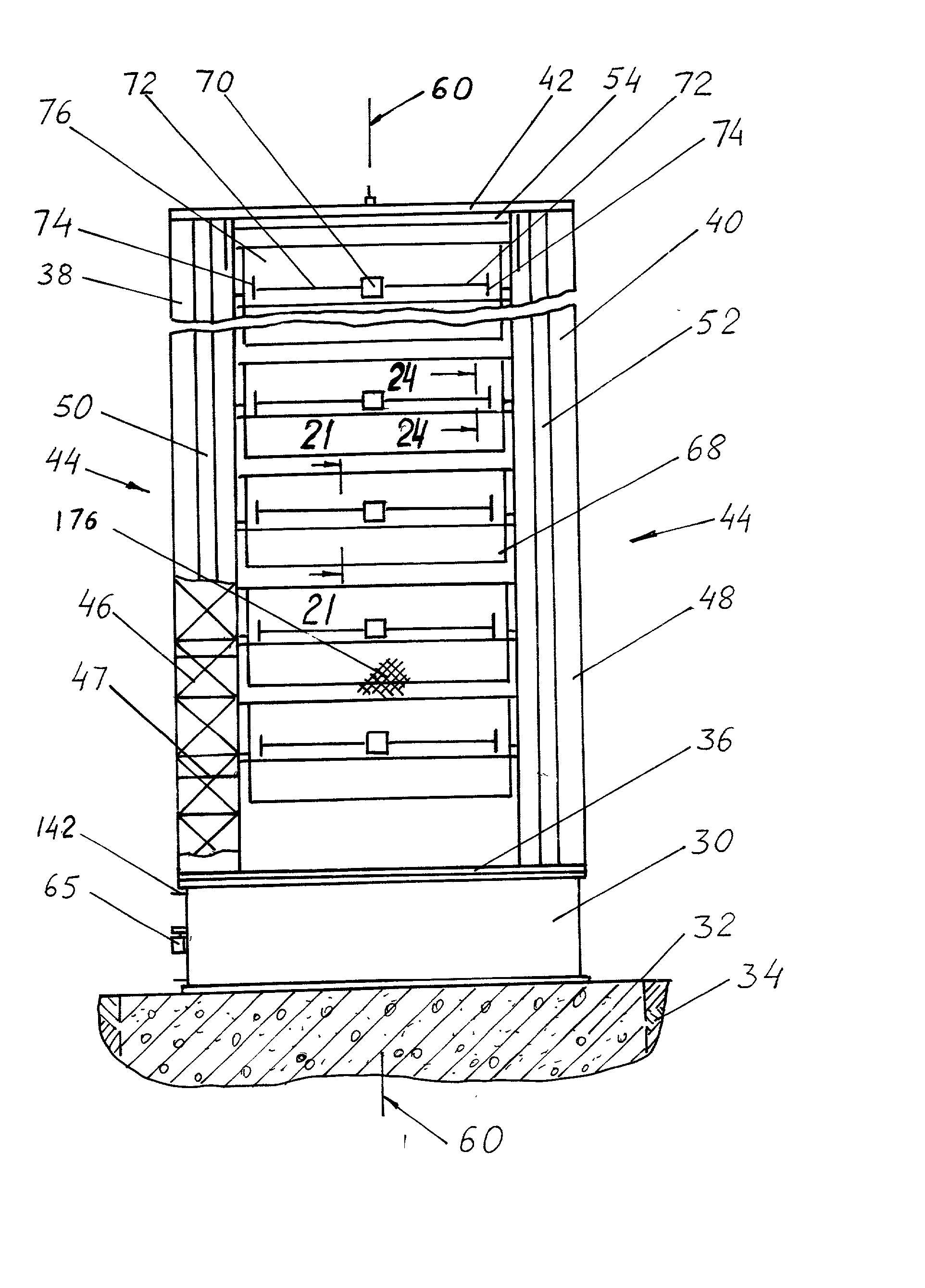
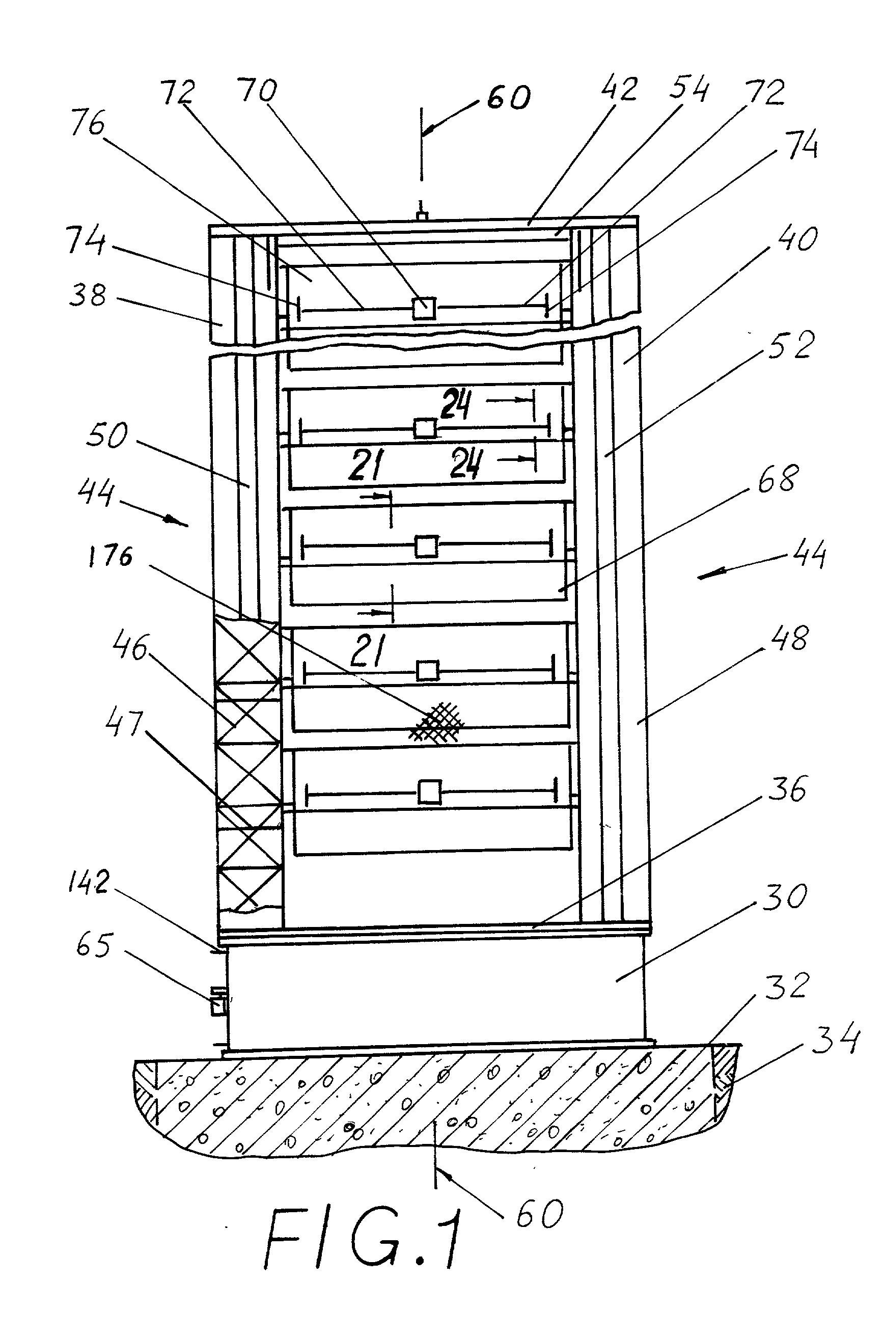
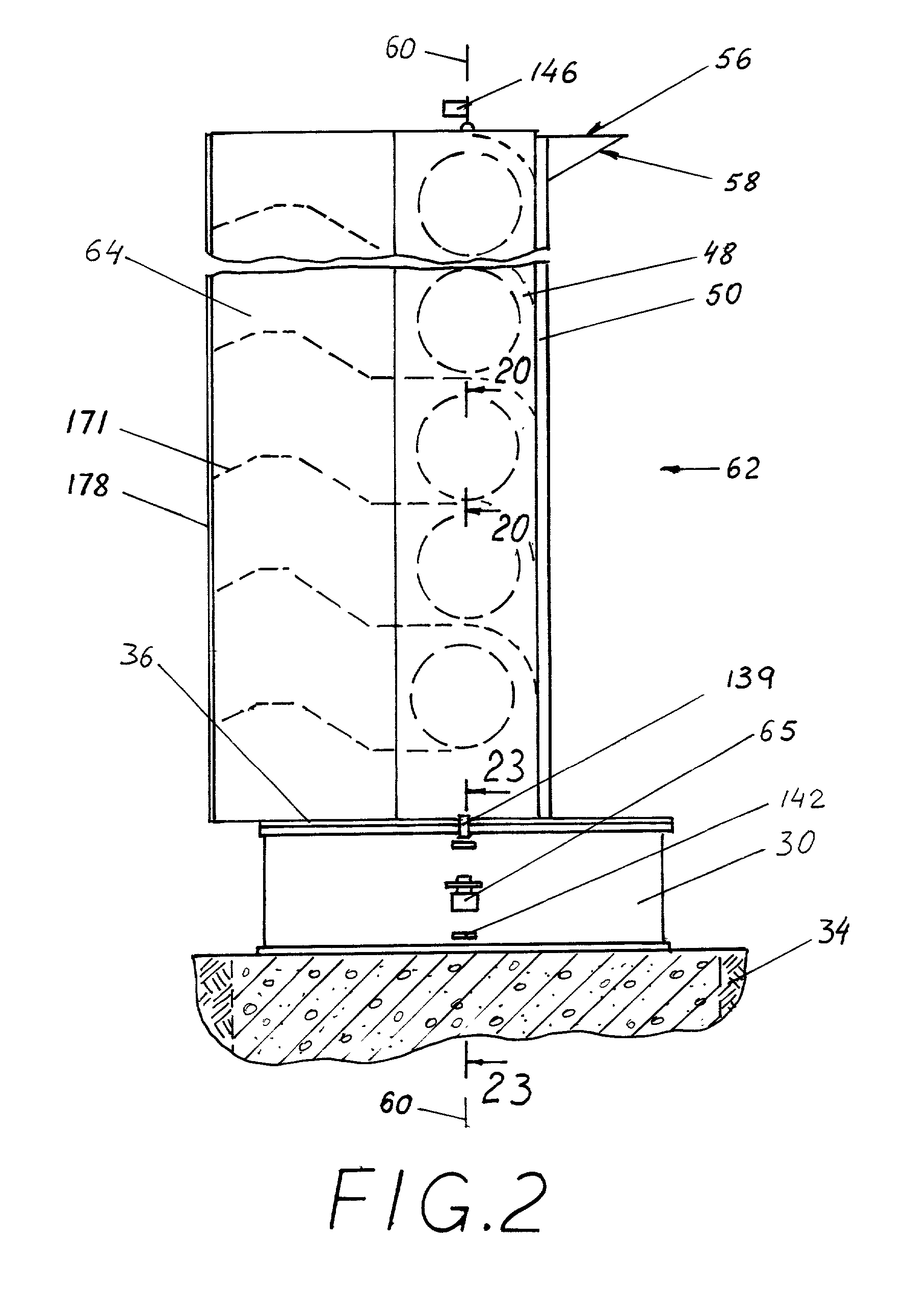
Of The Invention 1) Reference Numerals In Drawings 30 base 32 concrete frame 34 ground 36 horizontal platform 38 left tower 40 right tower 42 roof 44 housing 46 framework 47 floor 48 decorative panel 50 left shaft for elevators & stairs 52 right shaft for elevators & stairs 54 crane 56 beam 58 strut 60 vertical axis 62 general direction of the wind 64 wind tail 65 servomotor 65A electro-magnetic clutch 65B gear wheel 65C gear track 65D window 68 turbine 70 power drive 72 shaft 74 gear wheel 76 deflector 77 front cutting edge of deflector 78 back cutting edge of deflector 80 horizontal axis of rotation of rotor 82 left disk 84 right disk 86 tube 87 light framework 88 blade 89 strut 90 rotor 91 air gap between blade and tube 92 bearing 94 hub 96 collar 98 flange of hub 100 bolt 104 fixing plate 106 bracket 108 back deflector 112 governor 114 wheel of governor 116 track 117 front cutting edge of governor 118 gear track 120 permanent or electrical magnet 122 coil 123 air gap between mag...


PUM


Abstract

A wind power plant for producing electrical energy on a large scale, comprising a base, a housing, rotatable on said base around vertical axis. A wind tail, attached to the housing, rotate the housing toward direction of the wind, utilizing the power of the wind, and produces additional tunnel suction to the flow of the wind from front side to back side of the housing. A plurality of turbines, equipped with rotors with wide blades, is mounted inside the housing one above another. Deflectors cover from the wind the front side of the rotors above their axis of rotation while computer controlled governors are covering the remaining front side of the rotors below their axis of rotation, keeping steady the speed of rotation of the rotors. Working surfaces of turbines are covered from heavy snow and during the storm and protected from birds. Power plant saves the area of occupied land, utilizing higher speed of wind on higher elevations. It has an attractive aesthetic view and can be a landmark for the location where it is built.

Description

[0001] Not Applicable.STATEMENT REGARDING FEDERALLY SPONSORED RESEARCH OR DEVLOPMENT[0002] Not ApplicableREFERENCE TO A MICROFICHE APPENDIX[0003] Not Applicable.[0004] 1. Field of the Invention[0005] This invention relates to the wind power plants, specifically to such plants, which utilize a plurality of turbines, disposed in one housing with computerized control of work of the turbines, equipped with wide blades, having means for positioning the turbines toward direction of the wind and for accelerating the flow of the wind.[0006] 2. Brief Description of Prior Art[0007] The use of wind power as a source of energy, especially windmills, has a long history tracing for hundreds of years. But these windmills were designed for fulfilling specific needs on specific sites and could not provide electrical energy for large grid of electrical power because they had too small scale and could not meet necessary standard for electrical power because of constant change of their speed of rotatio...

Claims


Application Information

Patent Timeline
IPC IPC(8): F03D3/02F03D3/04
CPCF03D3/02F03D3/04Y02E10/74F03D3/0472F03D9/25F03D13/20Y02E10/728
Inventor SOSONKINA, YEVGENIYA
Owner SOSONKINA YEVGENIYA
Learn More