
Apparatus for testing memories with redundant storage elements

a technology of memory and apparatus, applied in the field of memory, can solve the problems of not having enough spare rows and columns to replace the three cells that are not in the first row, a relatively long time for the computer to read all of the data out of the error capture memory, and a substantial amount of time the computer needs to read the captured error data

Inactive Publication Date: 2003-02-13
CREDENCE SYSTEMS
View PDF4 Cites 9 Cited by
  • Summary
  • Abstract
  • Description
  • Claims
  • Application Information

AI Technical Summary

Problems solved by technology

However if we use the three spare columns to replace the columns containing the three cells in the first row, we may not have enough remaining spare rows and columns to replace the three cells that are not in the first row.
One problem with such a system is that since the error capture memory has to have as many cells as the memory being tested, it can take a relatively long time for the computer to read all of the data out of the error capture memory.
In a production environment where thousands of memories are being tested in succession, the total time the computer requires to read the captured error data is substantial and comprises a significant portion of the time required to test and repair the memories.
However since the test apparatus must provide a separate counter for each row and column of the array, the apparatus requires a large number of counters in order to test memories having a large number of rows and columns.

Method used


Image

  • Apparatus for testing memories with redundant storage elements
  • Apparatus for testing memories with redundant storage elements
  • Apparatus for testing memories with redundant storage elements

Examples


Embodiment Construction

(s)

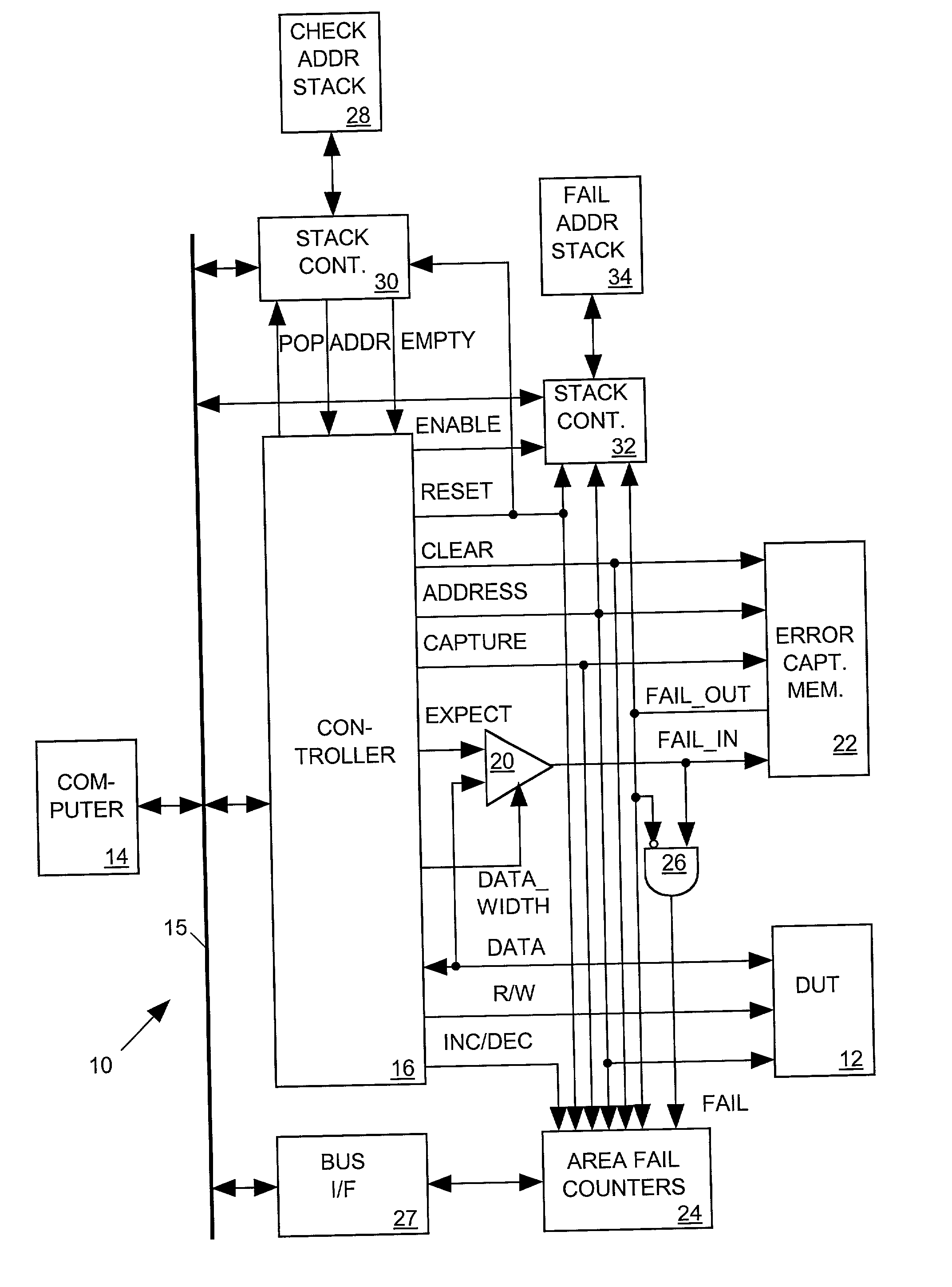
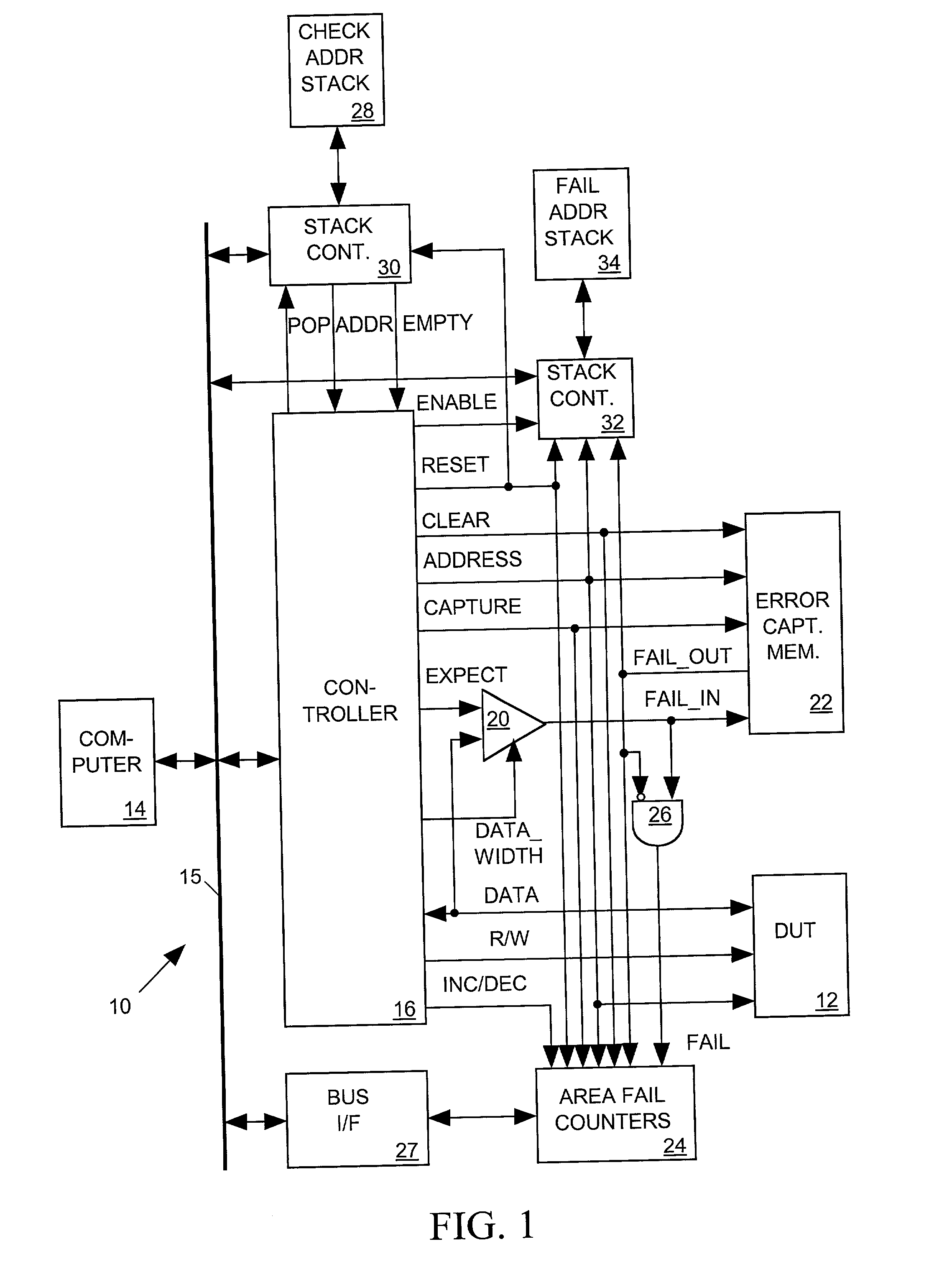
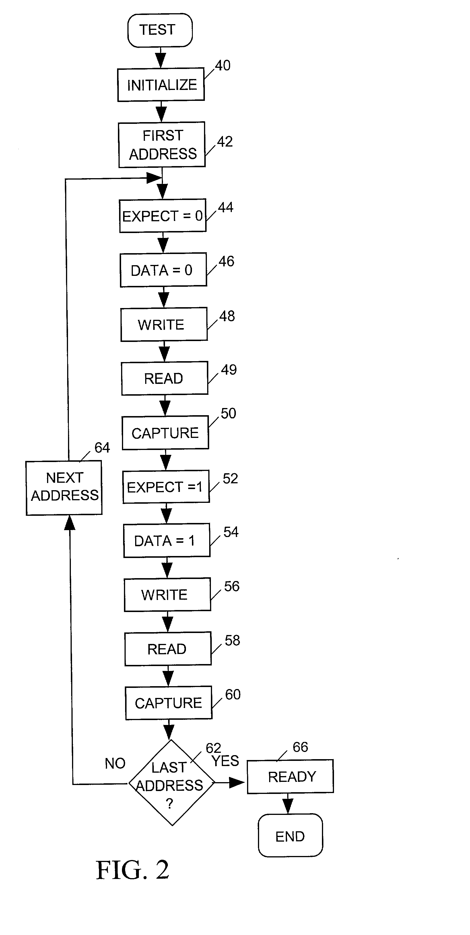
[0025] FIG. 1 illustrates in block diagram form a memory tester 10 in accordance with the present invention for testing a random access memory device under test (DUT) 12. DUT 12 includes an array of rows and columns of memory cells, each cell having a unique combination of row and column addresses and each cell storing a word of one or more data bits. DUT 12 also includes several spare rows and / or columns. When DUT 12 has defective memory cells, rows or columns containing those defective memory cells can be replaced with the spare rows or columns. The replacement may be carried out, for example, using a laser or other means to modify the RAM so that a spare row or column is addressed in lieu of a row or column containing the defective cell. Memory tester 10 tests DUT 12 to determine which cells of DUT are defective and provides data indicating test results to a computer 14 via a conventional computer bus 15. Computer 14 analyzes the data to determine how to allocate the DUT's spa...


PUM


Abstract

A memory tester tests a random access memory device under test (DUT) comprising addressable rows and columns of memory cells, and provides a computer with enough information to determine how to efficiently allocate spare rows and columns for replacing rows and columns containing defective memory cells. During a test the memory tester writes a "fail" bit into each address of an error capture memory (ECM) to indicate whether a correspondingly addressed memory cell of the DUT is defective. The tester also includes a set of programmable area fail counters, each for counting of the number of memory cells within a separately selected area of the memory's address space. After the test, the computer processes the counts to determine whether it needs to allocate the spare rows and columns and, in some cases, to determine how to allocate the spare rows and columns. When it cannot allocate spare rows and columns on the basis of the counts alone, the computer commands the tester to read the fail bits in selected areas of the ECM's address space to determine the addresses of the defective memory cells and to supply those addresses to the computer to enable it to determine how to allocate spare rows and columns.

Description

[0001] 1. Field of the Invention[0002] The present invention relates in general to memories having spare rows and columns of memory cells that can be used to replace rows and columns having defective cells, and in particular to an apparatus for testing such a memory and for generating data for facilitating allocation of spare rows and columns.[0003] 2. Description of Related Art[0004] A typical random access memory (RAM) includes an array of rows and columns of memory cells, each cell having a unique combination of row and column address. Many RAMs include redundant storage elements in the form of spare rows and columns of memory cells. When such a RAM is found to have a defective memory cell, a row or column containing that memory cell can be replaced with one of the RAM's spare rows or columns by using a laser or other means to alter the RAM so that the spare row or column is addressed in lieu of the row or column containing the defective cell.[0005] Each cell resides in one row a...

Claims


Application Information

Patent Timeline
IPC IPC(8): G11C29/56
CPCG11C29/56G11C2029/5606
Inventor OONK, JOHN MARK
Owner CREDENCE SYSTEMS
Learn More