Method for joint interpretation of multi-array induction and multi-component induction measurements with joint dip angle estimation
- Summary
- Abstract
- Description
- Claims
- Application Information
AI Technical Summary
Problems solved by technology
Method used
Image
Examples
Embodiment Construction
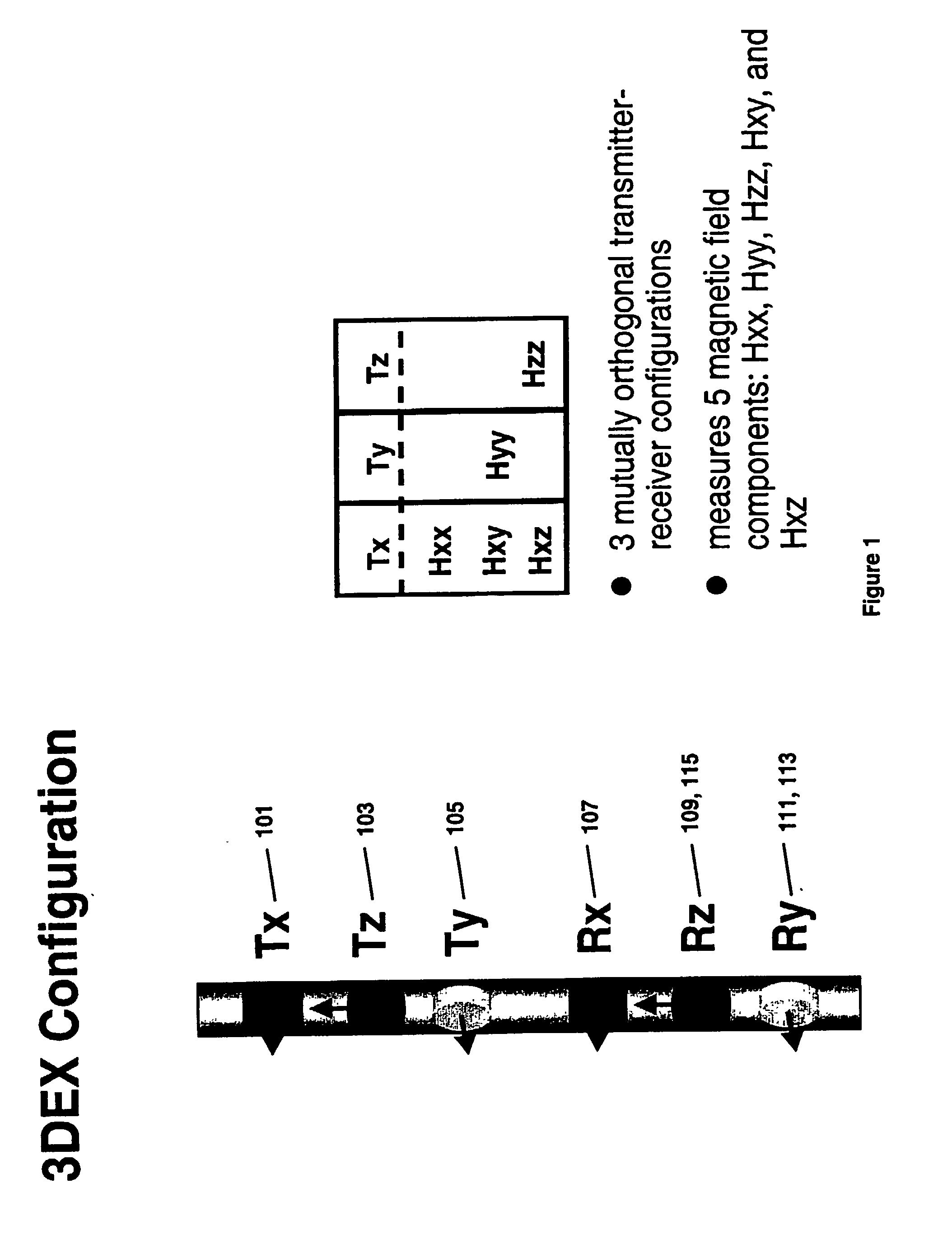
[0034] FIG. 1 shows the configuration of transmitter coils and receiver coils in a preferred embodiment of a multi-component measurement device, known as the 3DExplorer.TM. (3DEX.TM.) induction logging instrument of Baker Hughes. Three orthogonal transmitters 101, 103, and 105 that are referred to as the T.sub.x, T.sub.z, and T.sub.y transmitters are placed in the order shown. The three transmitters induce magnetic fields in three spatial directions. The subscripts (x, y, z) indicate an orthogonal system substantially defined by the directions of the normals to the transmitters. The z-axis is chosen to be along the longitudinal axis of the tool, while the x-axis and y-axis are mutually perpendicular directions lying in the plane transverse to the longitudinal axis. Corresponding to each transmitter 101, 103, and 105 are associated receivers 107, 109, and 111, referred to as the R.sub.z, R.sub.z, and R.sub.y receivers, aligned along the orthogonal system defined by the transmitter no...
PUM
 Abstract
Description
Claims
Application Information
 - R&D
- Intellectual Property
- Life Sciences
- Materials
- Tech Scout
- Unparalleled Data Quality
- Higher Quality Content
- 60% Fewer Hallucinations
Browse by: Latest US Patents, China's latest patents, Technical Efficacy Thesaurus, Application Domain, Technology Topic, Popular Technical Reports.
© 2025 PatSnap. All rights reserved.Legal|Privacy policy|Modern Slavery Act Transparency Statement|Sitemap|About US| Contact US: help@patsnap.com


