
Presentation system using laser pointer

a technology of laser pointer and projection system, which is applied in the field of projection system, can solve the problems that the measurement cannot be a basic measure, and the laser beam will be incident on the eye of a person in the audien

Inactive Publication Date: 2003-02-06
FUJI PHOTO OPTICAL CO LTD
View PDF6 Cites 93 Cited by
  • Summary
  • Abstract
  • Description
  • Claims
  • Application Information

AI Technical Summary

Benefits of technology

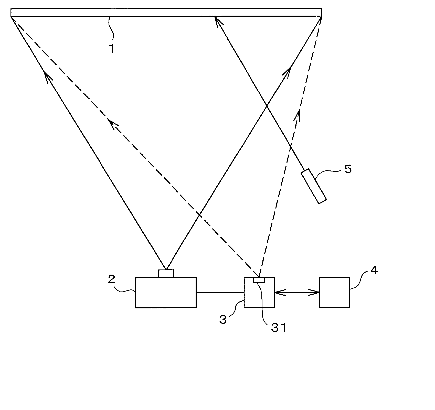
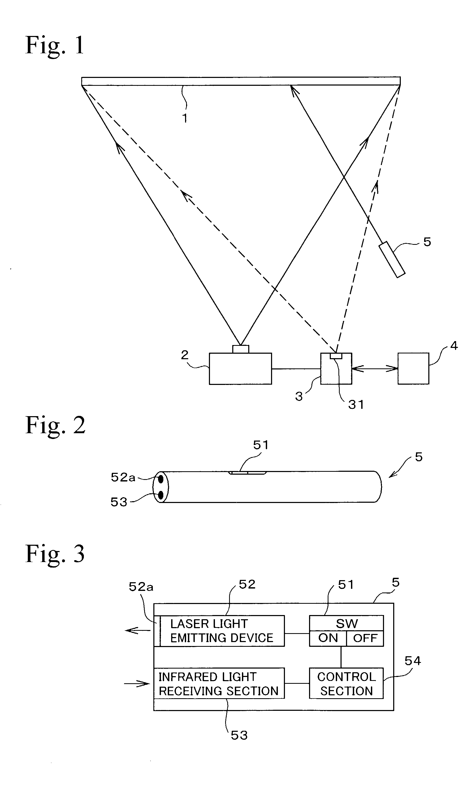
[0008] According to the first aspect of the invention, when the laser pointer is directed to the screen, the infrared light receiving section provided at the laser pointer receives infrared light reflected from the screen. At this time, laser beam is emitted from the laser pointer and the laser beam is projected onto the screen. On the other hand, when the laser pointer is directed away from the screen, the infrared light receiving section does not receive the infrared light reflected from the screen so that laser beam is not projected. That is, only when the laser pointer is directed toward the screen, a laser beam is projected. Accordingly, erroneous emission of laser beam is prevented beforehand so that a presentation can be performed safely.

Problems solved by technology

With such a laser pointer, there is a risk that the laser beam will be made incident on the eye of a person in the audience due to an erroneous emission.
In the safety measures disclosed in each of these publications, since a laser beam is emitted if the apparatus disclosed therein should not operate precisely, such a measure cannot be a basic measure.

Method used


Image

  • Presentation system using laser pointer
  • Presentation system using laser pointer
  • Presentation system using laser pointer

Examples


first embodiment

[0019] (1) First Embodiment

[0020] FIG. 1 conceptually shows an overall system of a first embodiment based upon a first aspect of the present invention. In the figure, reference numeral 1 denotes a screen, 2 denotes a liquid crystal projector which projects a liquid crystal image on the screen 1, 3 denotes an image processing section, and 4 denotes a personal computer (hereinafter, referred to as "PC"). Data for a liquid crystal image is produced in the PC 4, and the image data and various commands are inputted into the image processing section 3 from the PC 4. Then, image data processed in the image processing section 3 is input into the liquid crystal projector 2, and an image based upon the image data is projected as a visible image on the screen 1 from the liquid crystal projector 2.

[0021] In the image processing section 3, an infrared light emitting section (infrared light projector) 31 which projects infrared light on the entire surface of the screen 1 is provided. The waveleng...

second embodiment

[0027] (2) Second Embodiment

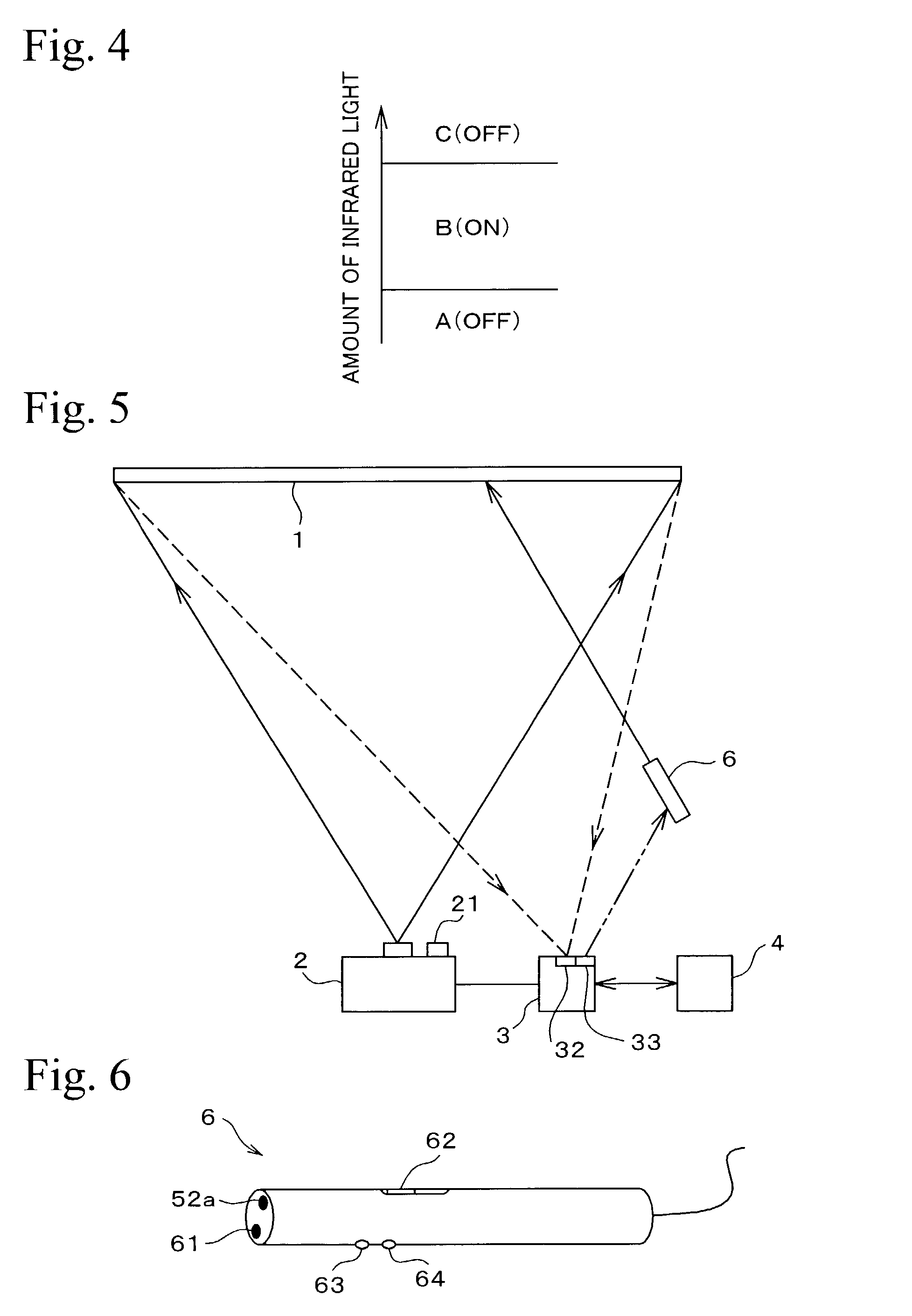
[0028] FIG. 5 schematically shows an overall system of a second embodiment of a second aspect of the present invention, where a screen 1, a liquid crystal projector 2, an image processing section 3, and a PC 4 are provided as in the first embodiment.

[0029] FIG. 6 is a perspective view showing a laser pointer 6 of a second embodiment, and FIG. 7 is a block diagram showing a configuration of the laser pointer 6. The laser pointer 6 is provided with a laser beam emitting device 52 and a laser beam emitting portion 52a, and it is further provided with an infrared light emitting portion (infrared light projector) 61. The projection direction of infrared light from the infrared light projecting section 61 is set in substantially the same direction as a projection direction of laser beam projected from the laser beam emitting section 52a. Accordingly, when the laser pointer 6 is directed towards the screen 1, infrared light is projected on the screen 1. The wave...


PUM


Abstract

A presentation system comprises a screen, a laser pointer operated by a user to project laser beam on the screen, and an infrared light projector for emitting infrared light on the entire surface of the screen. The laser pointer comprises an infrared light receiving section directed in the same direction as a projection direction of laser beam for receiving infrared light projected from the infrared light projector and reflected from the screen, and a control section for causing the laser pointer to project laser beam only while the infrared light receiving section is receiving infrared light.

Description

[0001] 1. Field of the Invention[0002] The present invention relates to a presentation system used in a lecture or the like which is performed while indicating a point on an image projected on a screen by a laser pointer, and in particular, relates to a development of a system for using a laser pointer safely.[0003] 2. Description of the Related Art[0004] In a case in which a presentation such as a lecture is performed using a liquid crystal projector or the like, a laser pointer for projecting laser beam on a screen to indicate a point for attention thereon is often used. With such a laser pointer, there is a risk that the laser beam will be made incident on the eye of a person in the audience due to an erroneous emission. In Japanese Patent Application Laid-Open (JP-A) 10-4228 publication, as a safety measure for avoiding such a risk, there has been disclosed a technique in which emission of laser beam is automatically turned on / off according to the brightness of an object (a scre...

Claims


Application Information

Patent Timeline
Patent Type & Authority Applications(United States)
IPC IPC(8): G09B19/00G02B27/20G03B27/20G06F3/033G06F3/042H04N5/74
CPCG02B27/20G03B27/20G06F3/03542G06F3/0386H04N5/74
Inventor HAMANA, AKINORINISHIMURA, MITSUYOSHI
Owner FUJI PHOTO OPTICAL CO LTD
Learn More