Method and device for transferring compact discs to a packaging line
- Summary
- Abstract
- Description
- Claims
- Application Information
AI Technical Summary
Benefits of technology
Problems solved by technology
Method used
Image

Examples
first embodiment
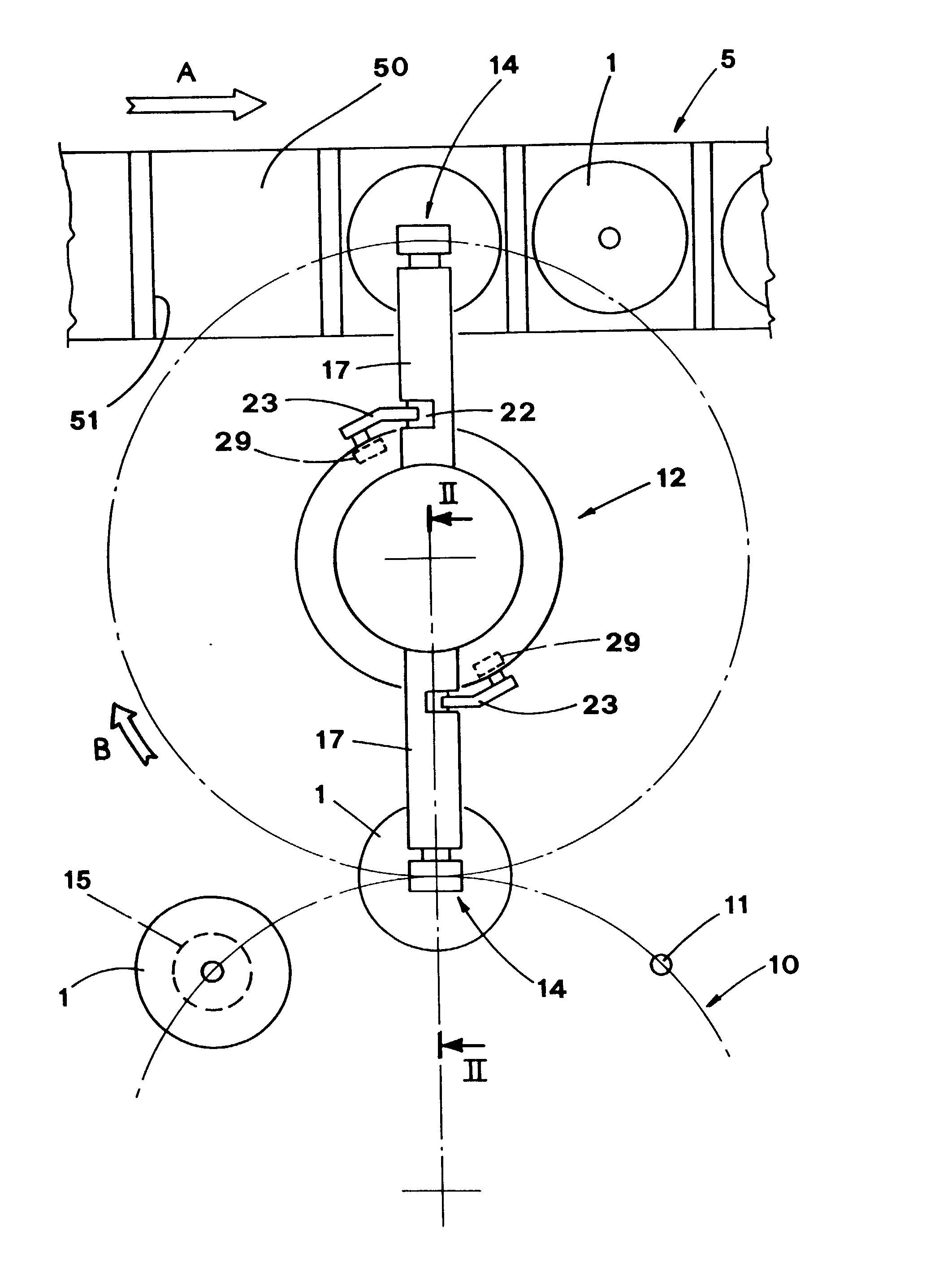
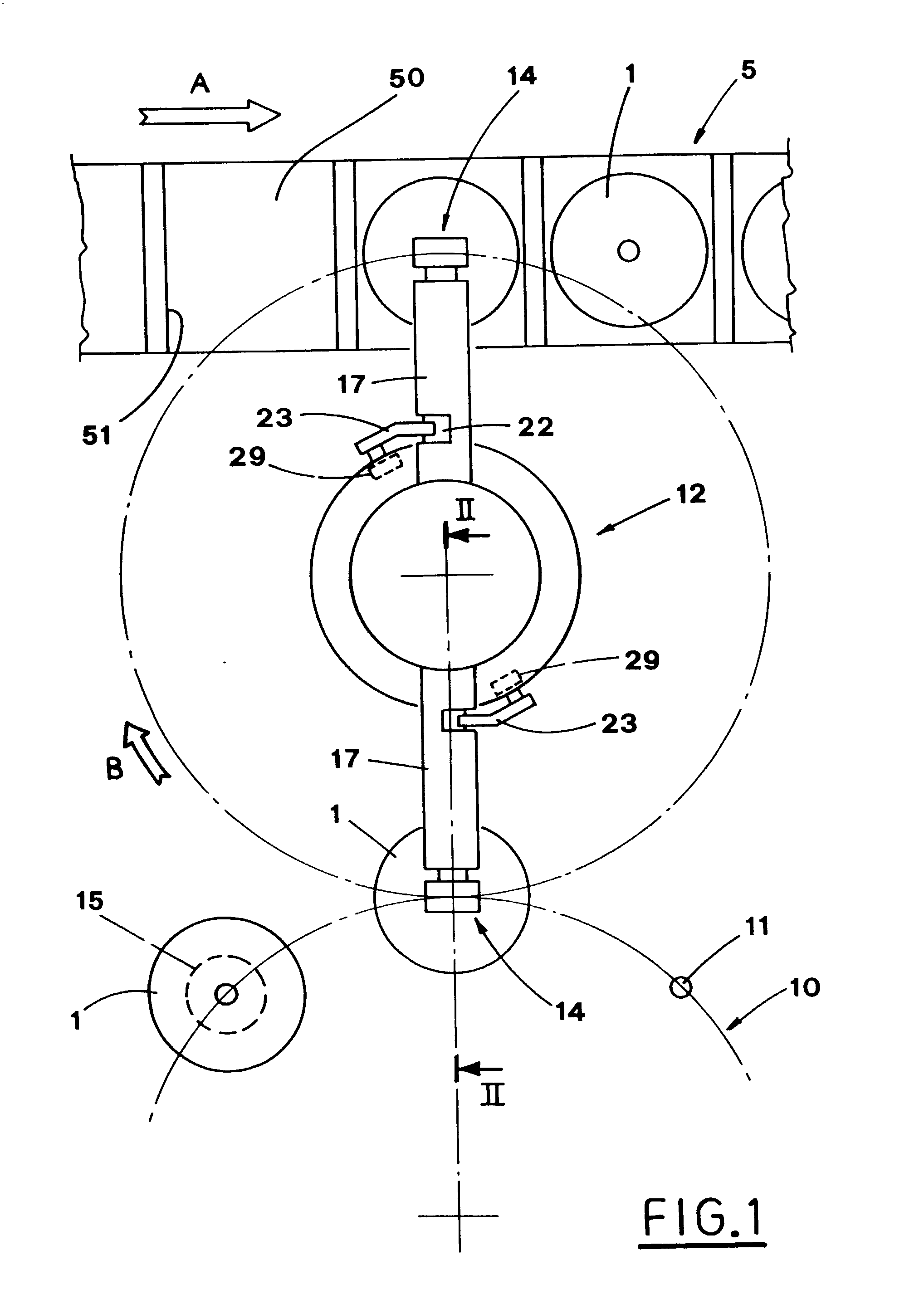
[0033] With particular reference to FIGS. 1 and 2, and to the invention, reference numeral 1 indicates compact discs to be packaged into relative envelopes.
[0034] The compact discs 1 to be introduced into the envelopes are taken from a carrousel magazine 10, rotating stepwise on a vertical axis, which is suitably oriented.
[0035] The compact discs 1 are piled up on loading members 15, which are carried on the edge of the carrousel magazine 10 and are equipped with a guiding shaft 11.
[0036] In the example shown in FIG. 1, the above mentioned rotation axis is parallel to the axis of the compact discs pile, and in particular it is substantially vertical.
[0037] The carrousel magazine 10 supplies a device 12 for taking and placing compact discs in an ordered way, onto a conveying line 5, which is operated to move continuously in direction indicated with the arrow A.
[0038] The conveying line 5 is situated beside a corresponding line for conveying envelopes, not shown, and moves synchronous...
second embodiment
[0080] FIGS. 9a, 9b, 9c and 10a, lob, 10c show the means operating the combined translation motion of the pick up groups 14 with respect to the drum 13.
[0081] According to this embodiment, the drum 13 features a circular head 45, which carries, along its edge in correspondence to each pick up group 14, a "V"-like cam 46, engaged by a roller 47 joined to a shaft 14a of the pick up group 14.
[0082] The shaft 14a slides inside a tube 48 in directions away from and towards the pile of compact discs.
[0083] The tube 48 is formed at the end of a lever 49, which is situated radially to the drum 13 and is moved angularly with respect thereto by suitable actuators, not shown.
[0084] Also in this case, in order to remove the compact discs 1, the pick up group 14 is brought, by the combined translation movements away from and towards the compact discs pile, first to an initial remote and forward position, due to the action of the cam 46 and along a circumference of the drum 13, due to the action ...
third embodiment
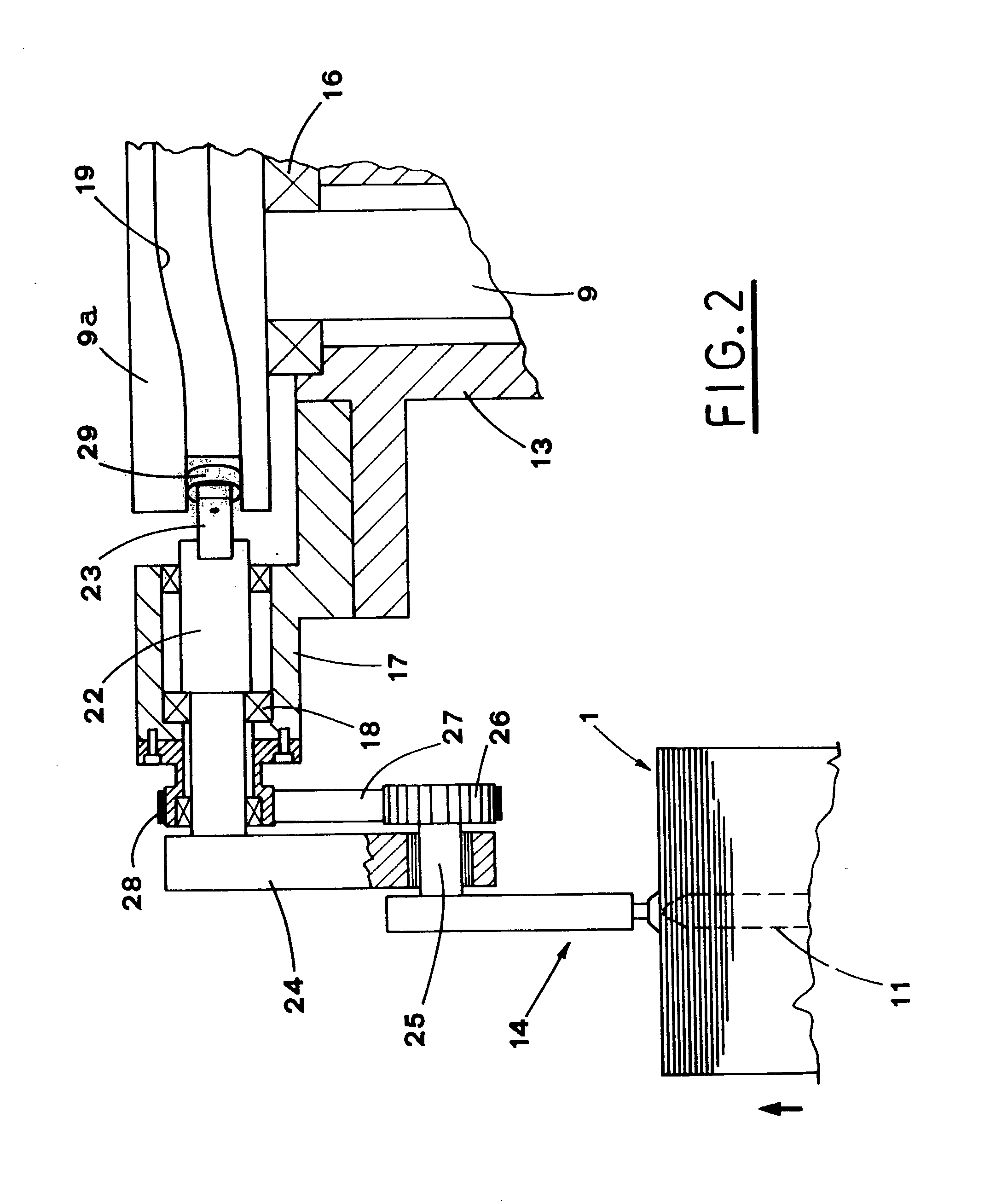
[0088] FIGS. 11 and 12 show the placing device 12.
[0089] According to this embodiment, a drum 113 rotates on a corresponding turret 109.
[0090] Each pick up group 14 is equipped with operating means 120, which it to the same combined translation motion in directions away from and towards the compact discs pile, and along the circumference of the drum 113.
[0091] In particular, the operating means 120 include a shaft 122, carried idle on its axis by a tube 117, which is integral with the drum 113 and radial thereto.
[0092] The outer end of the shaft 122 supports a transverse arm 124, whose other end features a through hole 124a.
[0093] Like in the first embodiment of the present invention, a spindle 25 passes through the hole 124a.
[0094] The spindle 25 carries, on its outer end the pick up group 14, and on its inner end, the toothed wheel 26.
[0095] Likewise, the toothed belt 27 connects the pulley 28 with the toothed wheel 26, which are aimed at maintaining substantially constant the tra...
PUM
 Abstract
Description
Claims
Application Information
 - R&D
- Intellectual Property
- Life Sciences
- Materials
- Tech Scout
- Unparalleled Data Quality
- Higher Quality Content
- 60% Fewer Hallucinations
Browse by: Latest US Patents, China's latest patents, Technical Efficacy Thesaurus, Application Domain, Technology Topic, Popular Technical Reports.
© 2025 PatSnap. All rights reserved.Legal|Privacy policy|Modern Slavery Act Transparency Statement|Sitemap|About US| Contact US: help@patsnap.com