
Holographic light panels and flat panel display systems and method and apparatus for making same

a technology of flat panel display and light panel, applied in the field of holographic, can solve the problems of inability to meet the needs of the user,

Inactive Publication Date: 2003-01-30
KREMEN STANLEY H
View PDF17 Cites 28 Cited by
  • Summary
  • Abstract
  • Description
  • Claims
  • Application Information

AI Technical Summary

Benefits of technology

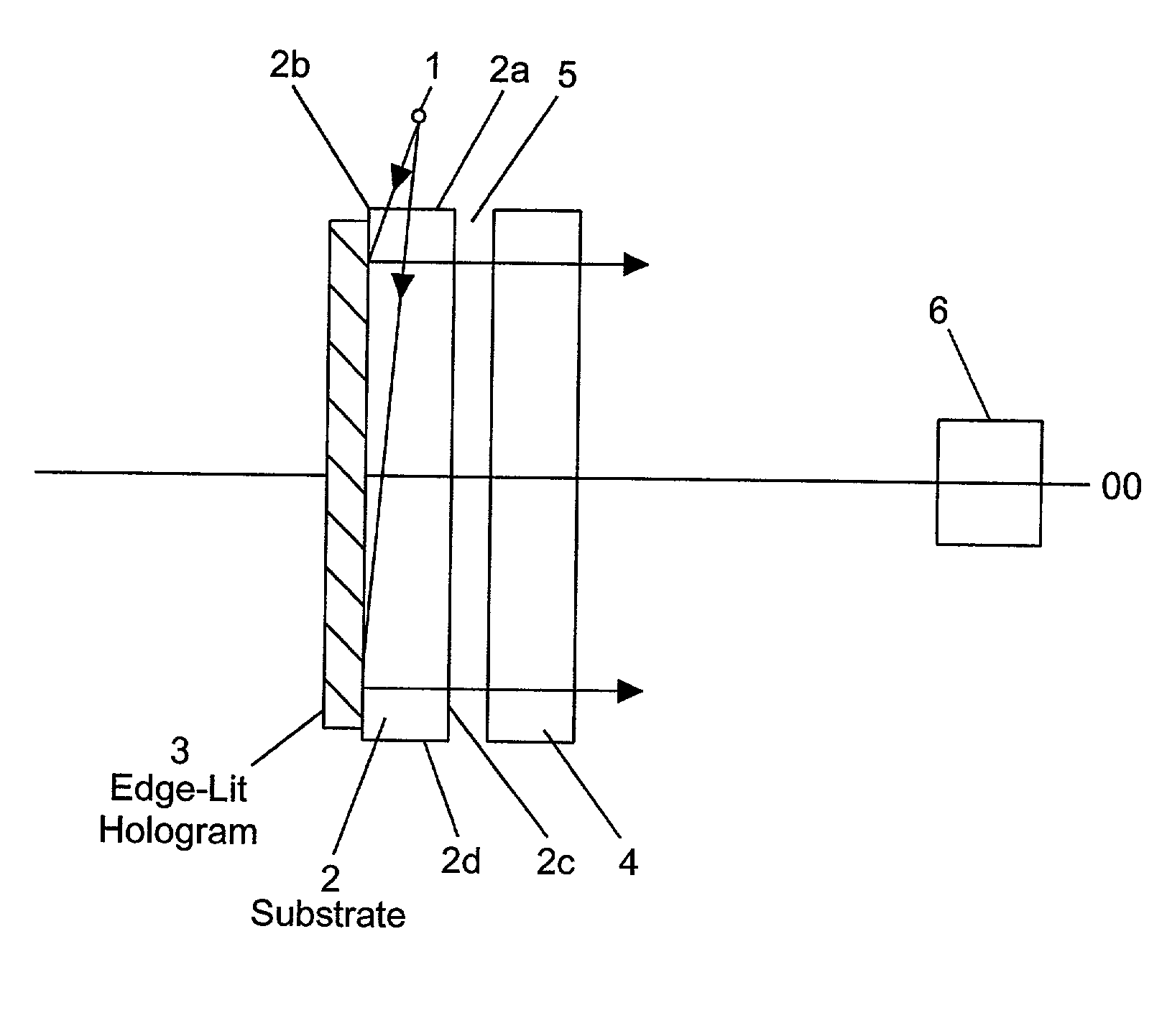
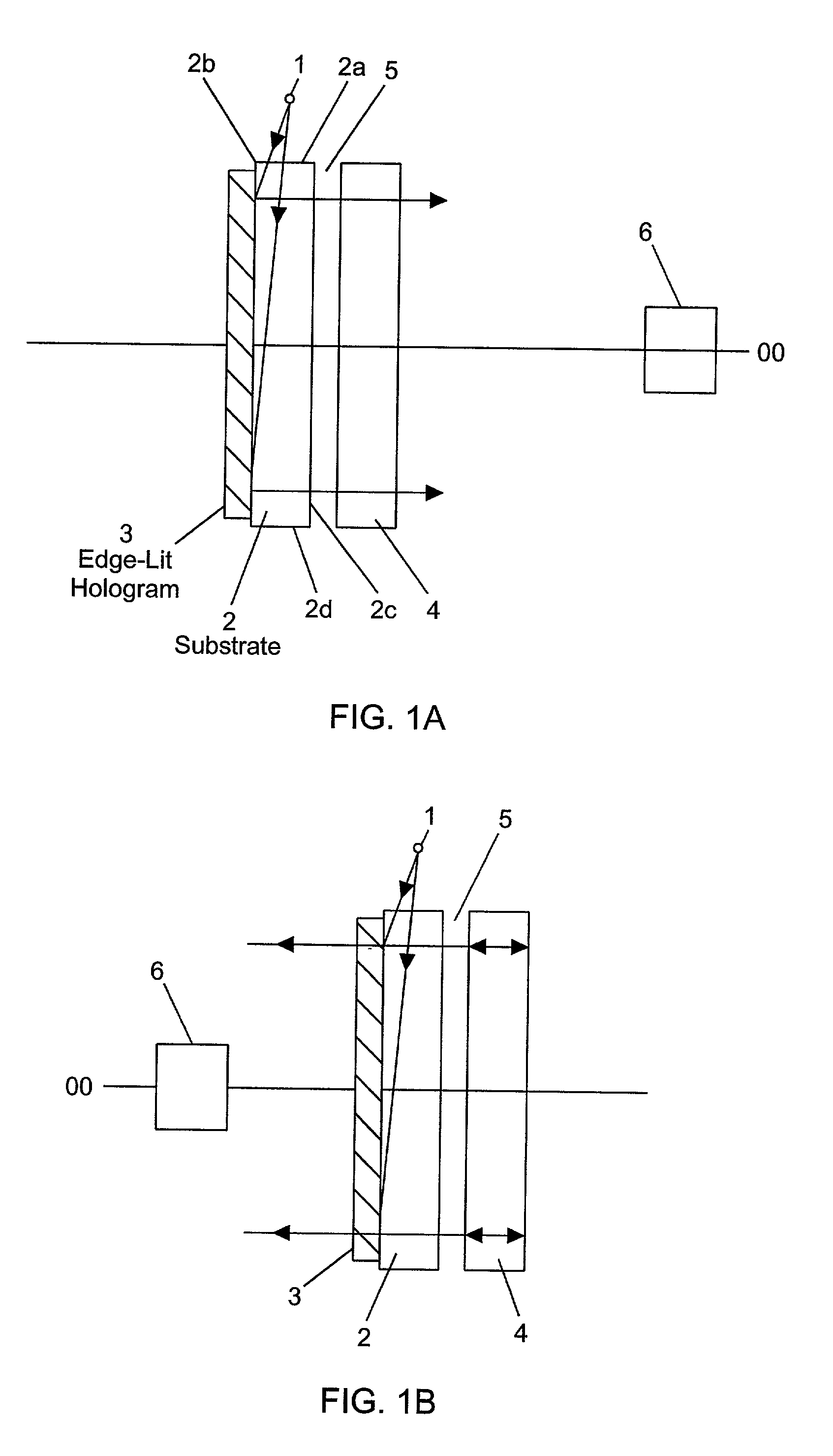
[0011] Accordingly, it is a primary object of the present invention to provide an edge-lit holographic illumination or light panel )HLP) which can be used in a diverse range of backlighting and frontlighting applications while avoiding the shortcoming and drawbacks of prior art holographic light panel systems.
[0019] A further objection of the present invention is to provide a holographic light panel which allows a significant reduction in the physical volume necessary for the illumination of flat panel displays, transparencies, holograms, and various other objects.

Problems solved by technology

Prior art optical schemes for achieving such illumination typically requires considerable packaging volume, can involve multiple optical elements, are costly and / or inefficient.
Backlighting with flat fluorescent lamps is not attractive because of problems with uniformity of light from the tubes and because the tubes are relatively bulky and require too much electrical power for the typical LCD environment (see e.g., Hathaway, Proc.
An additional problem with displays such as AMLCD's is that in order to spatially intensity modulate light from the backlighting system, a pixelated array of the discrete liquid crystal elements surrounded by opaque interstitial regions which reflect and / or absorb light incident thereon.
Most lighting solutions flood the entire display, both transmissive windows and opaque interstices, with light, thus wasting typically around 50% of the available light, which is lost to the opaque interstices.
This process is very inefficient and typically absorbs most of the incoming light, requiring stronger illumination light sources, and, in battery operated systems, wasting precious battery life.
First, the light diffractive transmission gratings employed in this prior art light panel exhibit significant objectionable dispersion of the incoming light, whereas in such an application strong wavelength selectivity would be more desirable. Additionally, the illumination light must necessarily make multiple bounces within the substrate, resulting in significant efficiency loss. The accuracy required of the incoming light for it to bounce correctly along the substrate and couple into the hologram is very difficult to achieve in commercial practice, making the holographic light panel impractical.

Method used


Image

  • Holographic light panels and flat panel display systems and method and apparatus for making same
  • Holographic light panels and flat panel display systems and method and apparatus for making same
  • Holographic light panels and flat panel display systems and method and apparatus for making same

Examples


case 1

[0091] Index Matching: Case 1

[0092] In U.S. application Ser. Nos. 08 / 594,715, 08 / 546,709 and 08 / 011,508, Applicants teach that for Case 1 recording situations, the highest quality edge-lit holograms can be achieved by carefully matching the index of refraction of the recording medium with the index of refraction of its associated substrate. The degree of matching required is a function of the steepness of the reference beam angle and the light transmission into the recording medium, which is derived by combining the well known Fresnel reflection equations with Snell's Law at the substrate-recording medium interface. In practice, the best index matching in this case is achieved by choosing a substrate whose index of refraction is equal to or slightly less than the index of refraction of the recording medium. For example, in accordance in with this index matching technique, Applicants have discovered that BK10 glass works well with DuPont holographic recording material designated HRF ...

case 2

[0094] Index Matching: Case 2

[0095] In U.S. application Ser. Nos. 08 / 594,715, 08 / 546,709 and 08 / 011,508, Applicants also teach that for Case 2 recording situations, it is best to use a "gradient-type" index matching region at the interface between the substrate and the recording medium. This type of indexing matching region can be achieved during the recording of edge illuminated holograms when using photopolymer recording materials which contain migratory monomers. During such recording process, applicants have discovered that under particular conditions the action of the signal wave (object beam) can increase the refractive index of the recording layer near the boundary between the recording material and the substrate by attracting migratory monomer toward this boundary. This increases the ability of the reference wave to couple into the recording medium when it is incident at an angle close to grazing incidence. At locations of high reference signal strength in the recording medi...


PUM


Abstract

An illumination panel for illuminating an object, comprising a substrate, a light diffractive grating and a light source. The substrate is made from an optically transparent material having first and second area surfaces disposed substantially parallel to each other and a light input surface for conducting a light beam into the substrate. The light diffractive grating is mounted to the first areal surface and has a slanted fringe structure embodied therein for diffracting the light beam falling incident thereto, along a first diffractive order of the slanted fringe structure. The light source produces a light beam for transmission through the input surface and direct passage through the substrate to the slanted fringe structure so as to produce an output light beam of areal extent that emerges from either the first or second areal surface along the first diffractive order, for use in illuminating an object. A spatial-intensity modulation panel can be mounted to the illumination panel to form a color image display device. In the illustrative embodiments, the light diffractive grating is a volume hologram that is pixelated and spectrally-tuned in order to carry out spectral filtering functions within the color image display device.

Description

BACKGROUND OF INVENTION[0001] 1. Field of Invention[0002] The present invention related to holographic light panels (HLPs) embodying edge-lit and steep reference angle holograms, for use in illuminating electronically-switched pixelated display screens (e.g., liquid crystal displays), flat panel displays, as well as transparencies and holograms, and also to methods of making such holographic light panels and the holograms embodied therein.[0003] 2. Brief Description of the Prior Art[0004] Many objects, such as transparencies or flat panel displays, require a broad area illumination source. Prior art optical schemes for achieving such illumination typically requires considerable packaging volume, can involve multiple optical elements, are costly and / or inefficient. Manufacturers of flat panel displays, and in particular active matrix liquid crystal displays (AMLCD's), strive for system designs which produce bright, uniform illumination, are thin, lightweight, inexpensive, and energy ...

Claims


Application Information

Patent Timeline
IPC IPC(8): A61B5/117F21V8/00G02B5/32G02B6/00G03C1/00G03C1/66G03C5/44G03H1/00G03H1/04G03H1/18G06K7/10G06V40/13G07C9/00
CPCA61B5/1172G02B5/32G02B6/0033G02B6/0036G02B6/0053G02B6/0068G02B6/0071G02B6/0073G03C1/00G03C1/66G03C5/44G03H1/0248G03H1/0408G03H2222/47G06K7/10663G06K7/10702G06K7/1098G06K9/00013G07C9/00158A61B5/745G03H2001/2226G07C9/37G06V40/13
Inventor METZ, MICHAEL H.PHILLIPS, NICHOLAS J.COLEMAN, ZANECAULFIELD, JOHNFLATOW, CARL
Owner KREMEN STANLEY H
Learn More