


Quick Research
Generate reliable direction feasibility study reports for your R&D in just a few steps.

Technical Q&A
Discover and master advanced knowledge NOW. Basics, ideas, possibilities, all at once.

Find Solutions
As an expert in R&D theories, this can generate solutions to your technical problems instantly.

Evaluate Feasibility
Analyze your overall solution with one click, know your potential R&D risks in advance.

Monitor Landscape
Get weekly tech updates, stay abreast of the latest tech innovations and key insights.
Motor vehicle alternator
- Summary
- Abstract
- Description
- Claims
- Application Information
AI Technical Summary
Benefits of technology
Problems solved by technology
Method used
Image


Examples
first embodiment
[0108] FIGS. 5 to 8 illustrate this advantageous characteristic for a six-phase coil, in a first embodiment in which the slots L contain four conductor elements arranged over four layers C1 to C4.
[0109] FIG. 5 presents a six-phase alternator stator including a body 18 comprising, in the above-mentioned way, a pack of plates complete with slots L traversed by electrically conducting elements 20 here called pins.
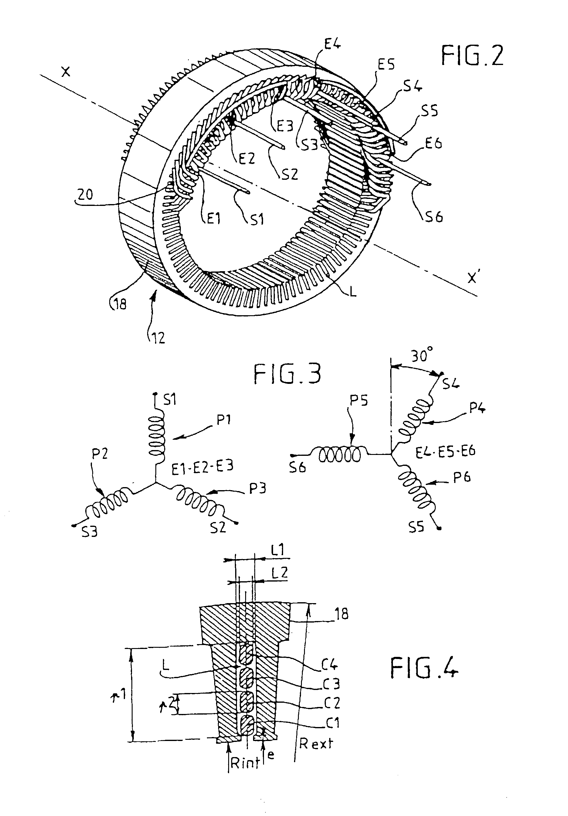
[0110] The stator coil of the phases includes, on a first axial side 18a of the body 18, the first bun 24 which brings together all the heads 20c of all the pins as well as the phase outlet [sic] S1 to S3 respectively for a first coil including a first series of three phases P1 to P3, and S4 to S6 for the second coil including the second series of three phases P4 to P6, the stator coil of the six-phase type being made up, in the manner stated above, from the two series of three phases mounted in star mode and offset by 30.degree. electrically as represented in FIG. 3. The bun ...
second embodiment
[0124] FIGS. 9 and 10 illustrate the invention in which the slots L contain six conductor elements arranged over six layers C1 to C6.
[0125] The head of a pin of the imbricated type has been represented at 37, and the head of a pin of the undulating type at 38, and the head of a third pin at 39, this head 39 straddling above the heads 35 and 36 as FIG. 9 shows.
[0126] It is quite obviously possible to have the reverse arrangement, the head 37 belonging to a pin of the undulating type and the head 38 belonging to a pin of the imbricated type.
[0127] The said three pins extend between a slot Lk and a slot Lk+6, in the case of a six-phase coil. The separation between these two slots would, obviously, be different if the stator included a different number of phases.
[0128] The head 37 joins a branch located on the layer C3 of the housing Lk to a branch located on the layer C5 of the housing Lk+6. In parallel, the head 38 joins a branch located on the layer C2 of the housing Lk to a branch l...
third embodiment
[0132] FIGS. 11 and 12 illustrate the invention in which the slots L contain eight conductor elements arranged over eight layers C1 to C8.
[0133] The head of a pin of the imbricated type has been represented at 40, the head of a pin of the undulating type at 41, the head of a pin of the imbricated type at 42, and the head of a pin of the undulating type at 43.
[0134] Conversely, the head 40 may belong to a pin of the undulating type, the head 41 then belonging to a pin of the imbricated type.
[0135] Likewise, the head 42 may belong to a pin of the undulating type, the head 43 then belonging to a pin of the imbricated type.
[0136] The heads 42 and 43 pass straddling over the heads 40 and 41.
[0137] The said four pins extend between a slot Lk and a slot Lk+6, in the case of a six-phase coil. The spacing between these two slots would, needless to say, be different if the stator included a different number of phases.
[0138] The head 40 joins a branch located on the layer C4 of the housing Lk ...
PUM
 Abstract
Description
Claims
Application Information
 - R&D Engineer
- R&D Manager
- IP Professional
- Industry Leading Data Capabilities
- Powerful AI technology
- Patent DNA Extraction
Browse by: Latest US Patents, China's latest patents, Technical Efficacy Thesaurus, Application Domain, Technology Topic, Popular Technical Reports.
© 2024 PatSnap. All rights reserved.Legal|Privacy policy|Modern Slavery Act Transparency Statement|Sitemap|About US| Contact US: help@patsnap.com