Modular adaptive optical subsystem for integration with a fundus camera body and CCD camera unit and improved fundus camera employing same

Inactive Publication Date: 2003-01-09
ADAPTIVE OPTICS ASSOC
View PDF0 Cites 88 Cited by
  • Summary
  • Abstract
  • Description
  • Claims
  • Application Information

AI Technical Summary

Benefits of technology

[0169] Such high resolution image data (and pictures) reveal details of the structure of the retina that are not possible to obtain without the use of the wavefront sensor-based adaptive optical subsystem. Moreover, provided with such high-quality images (and pictures), practitioners can detect diseases earlier. For example, glaucoma damage can be detected only after prolonged destruction of the retina's nerve fiber layer. Such high quality images (and pictures) enable a practitioner to view details of the retina's nerve fiber layer for early detection of glaucoma. In addition, such high quality images (and pictures) enable practitioners to chart more precisely the retinal blood vessel damage resulting from diabetes and other diseases.
[0171] In addition, the ophthalmic imaging instrument of the present invention preferably includes an observation source that is used during an observation mode of operation to view (observe) the eye through a view finder, which expands the potential useful applications of the ophthalmic imaging instrument.
[0173] In another aspect of the present invention, the optical subsystem, wavefront sensor-based optical subsystem and imaging subsystem of the ophthalmic imaging instrument (e.g., fundus camera) of the present invention are packaged in separate and distinct modular housings that interface via detachable connectors. In addition, the optical components of these modules are designed such that either the wavefront sensor-based adaptive optical subsystem or the imaging subsystem can be selectively interfaced directly to the optical subsystem (or directly to a relay lens adapter). Alternatively, the wavefront sensor-based optical subsystem and imaging subsystem may be packaged in a module housing separate and distinct from a module housing for the optical subsystem and interfaces thereto by detachable connectors. Such modular designs enables flexibility in meeting changing user demands.

Problems solved by technology

Current fundus cameras suffer from the problem that the aberrations of the eye limit the resolution of the camera.
More specifically, defocus such as myopia (near-sightedness) or hyperopia (far-sightedness) and astigmatism as well has many other higher order aberrations not only blur images formed on the retina (thus impairing vision), but also blur images taken of the retina of the human eye.
Such a design significantly increases the complexity and cost of the system.
In addition, the retinal imaging method and apparatus Williams and Liang cannot correct for aberrations (such as those due to blinking or accommodation) that occur after the wavefront sensing and compensation operations are complete (for example, during the subsequent imaging operations).
In addition, the retinal imaging method and apparatus of Williams and Liang does not permit the user to view (observe) the ocular fundus through a view finder, which limits the applications of the retinal imaging method and apparatus of Williams and Liang.
In addition, the Schack-Hartmann wavefront sensor of the retinal imaging apparatus of Williams and Liang is susceptible to the dot crossover problem.
Such overlap (or crossover) introduces an ambiguity in the measurement that must be resolved, or an error will be introduced.
Other ophthalmic imaging instruments (such as corneal topographers, retinal topographers, corneal imaging devices and retinal imaging devices) suffer from these same limitations.
In addition, current ophthalmic examination instruments (including retinoscopes, autorefractors, slit lamps and other indirect ophthalmoscopes) do not measure and characterize the higher order aberrations of the human eye, which may be required for adequately diagnosing and treating the patient.

Method used


Image

  • Modular adaptive optical subsystem for integration with a fundus camera body and CCD camera unit and improved fundus camera employing same
  • Modular adaptive optical subsystem for integration with a fundus camera body and CCD camera unit and improved fundus camera employing same
  • Modular adaptive optical subsystem for integration with a fundus camera body and CCD camera unit and improved fundus camera employing same

Examples


Embodiment Construction

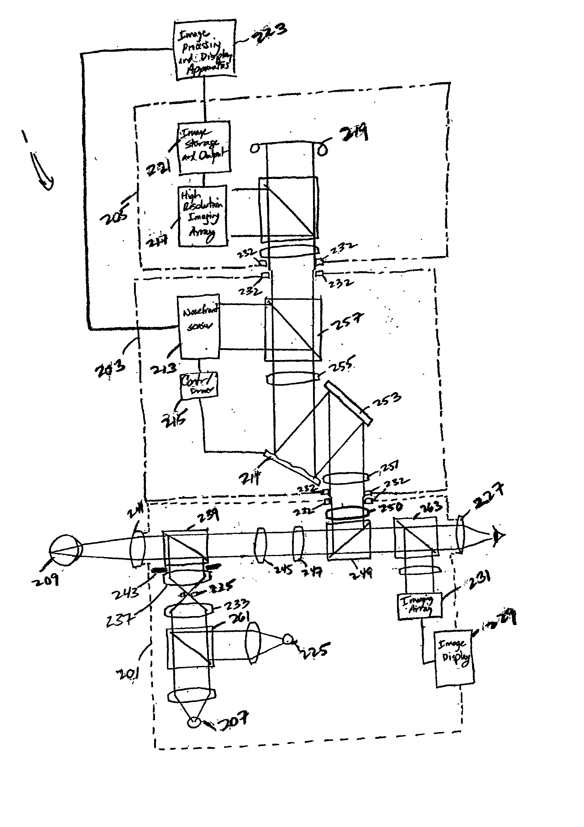
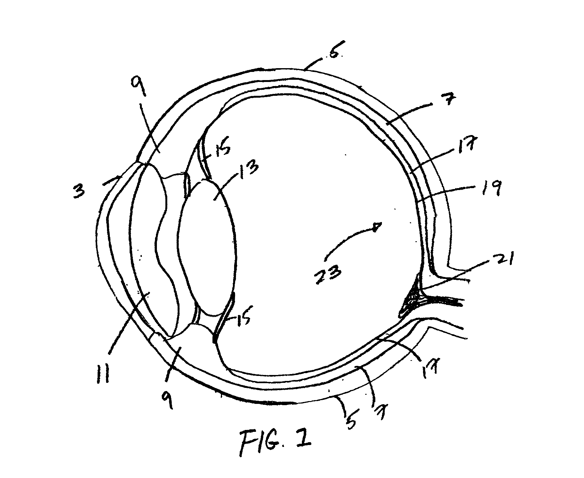
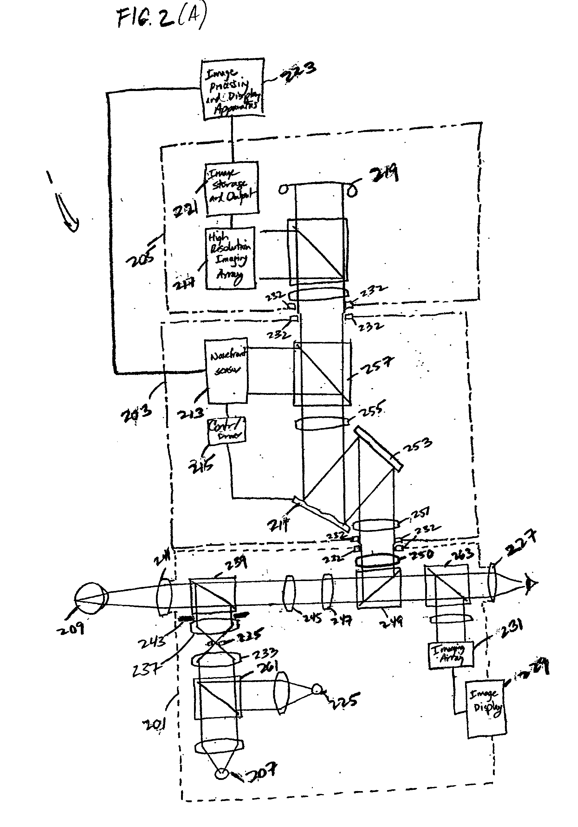
[0056] Referring to the figures in the accompanying Drawings, the preferred embodiments of the ophthalmic instruments of the present invention will be described in greater detail, wherein like elements will be indicated using like reference numerals.

[0057] According to the present invention, an ophthalmic imaging instrument includes a wavefront sensor-based adaptive optical subsystem that measures phase aberrations in reflections derived from light produced by an imaging light source and compensates for such phase aberrations when capturing images of reflections derived from light produced by the same imaging light source. For descriptive purposes, the wavefront sensor-based adaptive optical ophthalmic imaging instrument as described below comprises a fundus camera; however the present invention is not limited in this respect and is broadly applicable to any ophthalmic imaging instrument that captures images of the eye, including corneal topographer, retinal topographer, corneal ima...


PUM


Abstract

A modular fundus camera including an adaptive optical module that detachably interfaces to a fundus camera body and image capture subsystem. The fundus camera body directs light produced from a first light source into the human eye and that collects and collimates retinal reflections. The adaptive optical module includes a wavefront sensor, controller and phase-compensating optical element. The wavefront sensor measures phase aberrations in the retinal reflections and operates in a closed-loop fashion with the controller to control the phase-compensating optical element to compensate for such phase aberrations to produce phase-compensated retinal reflections for output to the image capture subsystem.

Description

[0001] The present application is related to U.S. application Ser. No. 09 / 874,403, entitled "Ophthalmic Imaging Instrument Having An Adaptive Optical Subsystem That Measures Phase Aberrations in Reflections Derived From Light Produced By An Imaging Light Source And That Compensates For Such Phase Aberrations When Capturing Images of Reflections Derived From Light Produced By The Same Imaging Light Source," by Bruce M. Levine; U.S. application Ser. No. 09 / 874,404, entitled "Ophthalmic Instrument Having An Integral Wavefront Sensor and Display Device That Displays A Graphical Representation of High Order Aberrations of the Human Eye Measured by the Wavefront Sensor," by Bruce M. Levine; and U.S. application Ser. No. 09 / 874,903, entitled "Ophthalmic Instrument Having An Integral Wavefront Sensor and Display Device That Displays A Graphical Representation of High Order Aberrations of the Human Eye Measured by the Wavefront Sensor," by Bruce M. Levine, each Application filed Jun. 5, 2001...

Claims


Application Information

Patent Timeline
IPC IPC(8): A61B3/103A61B3/12A61B3/14A61F9/008
CPCA61F9/008A61F2009/00846A61F2009/00848A61F2009/00855A61F2009/00863A61F2009/00872A61F2009/00882A61B3/103
Inventor LEVINE, BRUCE MARTIN
Owner ADAPTIVE OPTICS ASSOC
Why Eureka
Try Eureka