
Cable connecting device

a technology of connecting device and cable, which is applied in the direction of connection contact material, connection device connection, electric discharge lamp, etc., can solve the problems of low efficiency, laser incurring high cost, and requiring laser to be used as signal generator

Inactive Publication Date: 2002-12-05
TELEFON AB LM ERICSSON (PUBL)
View PDF1 Cites 2 Cited by
  • Summary
  • Abstract
  • Description
  • Claims
  • Application Information

AI Technical Summary

Benefits of technology

[0007] The object of the present invention is flus to improve signal qualities in the transmission of signals from a cable to a receiving unit.
[0009] Another advantage is that the surface at the ends of the cable conductors are cleaned automatically by the movement and deformation of the intermediate resilient material that results from the pressure exerted when assembling the cable connecting device to the receiving unit.
[0011] Yet another advantage resides in simplified assembly of cable and connector, resulting in greater economic gain.

Problems solved by technology

One drawback with fibre optics, however, is that a Fibre optic transmission requires a laser to be used as a signal generator.
A laser incurs a high cost and, moreover, has low efficiency since a large amount of the energy required by the laser is converted to heat.
One drawback with the solution taught by the U.S. patent specification resides in the length of mutually separated cable conductors required from the cable to the electric contact device in order to enable the conductors to be fitted to said device.
The fact that the cables are free-laid means that the relative order of said cable conductors before being freed is disturbed.
Impedance matching is impaired when the order of the cable conductors is disturbed, particularly in the case of twisted paired cables.
Moreover, the risk of crosstalk increases when the cable conductors are too close together.
Another drawback with the solution taught by the U.S. patent specification resides in the joining device to which the electric connecting device is joined between the cable conductors and a device that receives the connecting device.
This intermediate matching device involves an additional signal transition and causes interference in the signal transmission between cable and receiving unit, which results in poorer impedance matching and signal quality, and also in crosstalk in the contact device.
One problem with the solution taught in this U.S. patent specification resides in poor contact qualities when fitting the connecting device to the device that receives said contact-receiving device This results in signal disturbances.
Although the joining device provides assistance when fitting the cable connecting device to the receiving unit, it also causes signal disturbances at the same time.

Method used


Image

  • Cable connecting device
  • Cable connecting device
  • Cable connecting device

Examples


Embodiment Construction

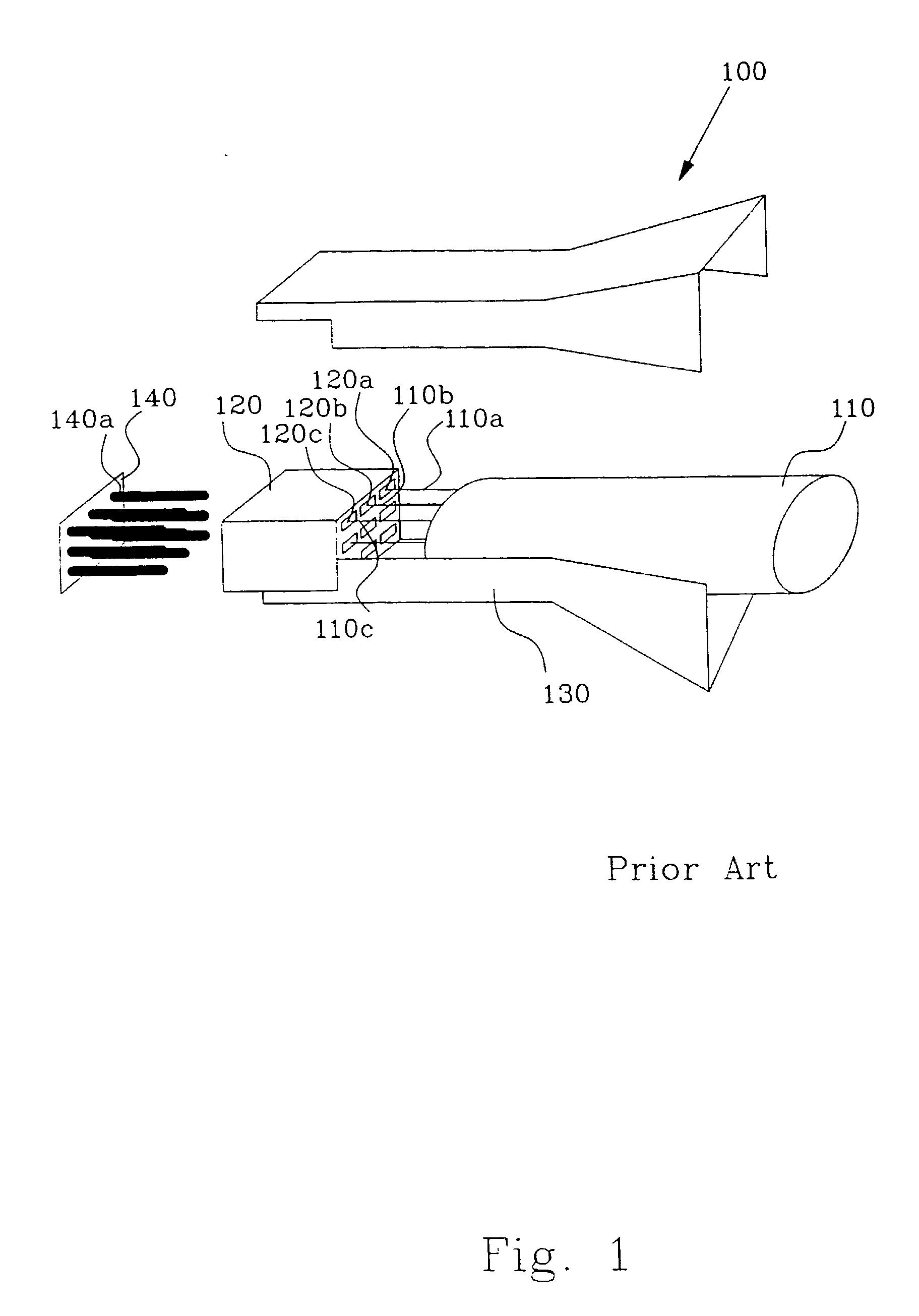
[0019] FIG. 1 illustrates an example of an earlier known cable connecting device 100. The prior art device includes a protective casing 120 and a conductor joining device 120 connected between a cable 110 and a unit 140 that receives said cable connecting device. The cable 110 includes electrical conductors 110a, 10b and 110c. The conductor joining device 120 includes electrically conductive connection forks or sleeves 120a, 120b and 120c which extend from an input side to an output side opposite to the input side of said device 120. The electric conductors 110a, 110b, 110c are connected to the connecting forks 120a, 120b, 120c of the device 120 on its input side. In order to be able to fit the cable conductors 110a, 110b, 110c to the connecting forks 120a, 120b, 120c, it is necessary for the cable 110 to be spaced from the conductor connecting device 120. In this respect, the separated or free-laid conductors are located in the air gap between cable and device. The distance require...


PUM


Abstract

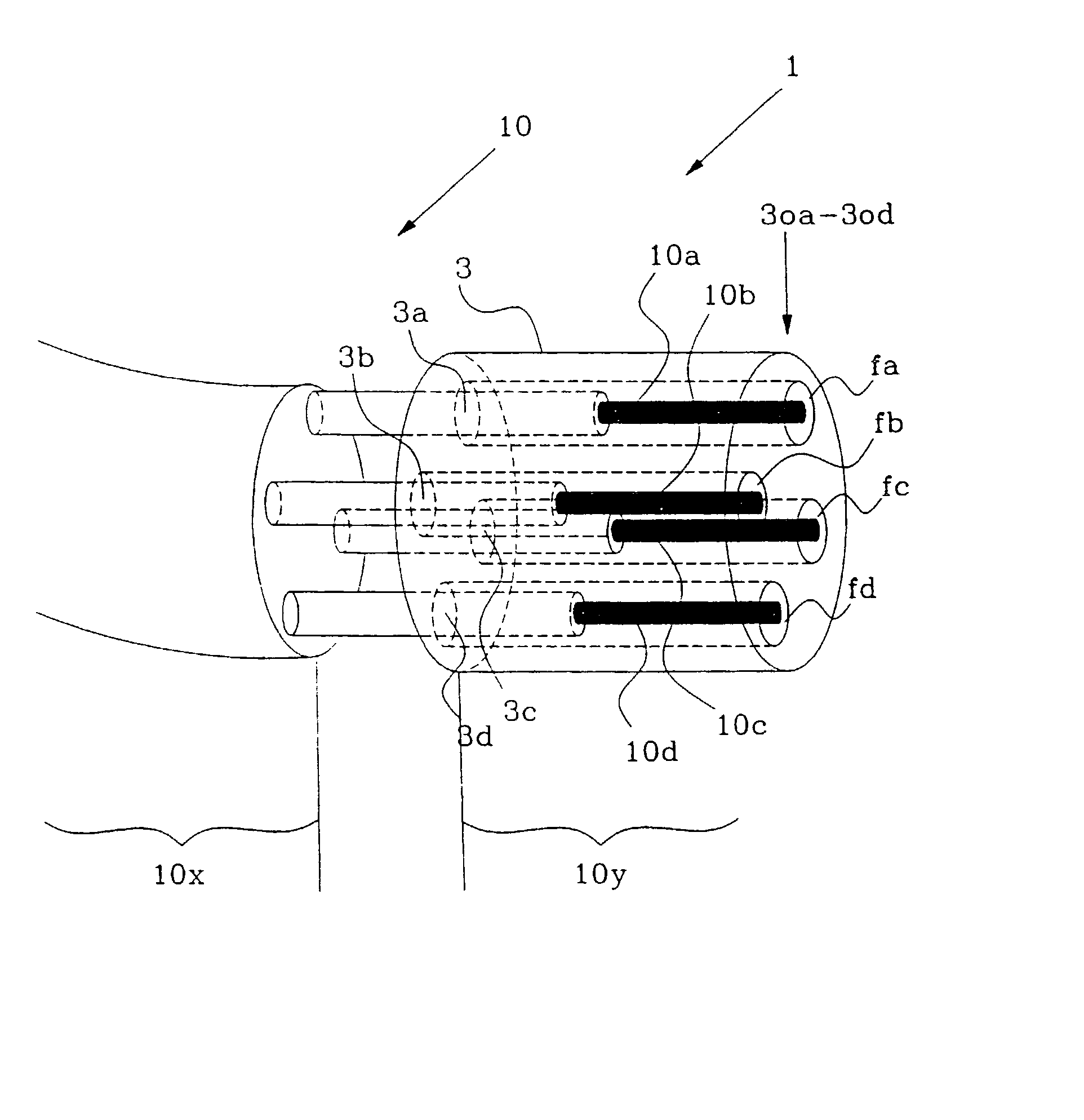
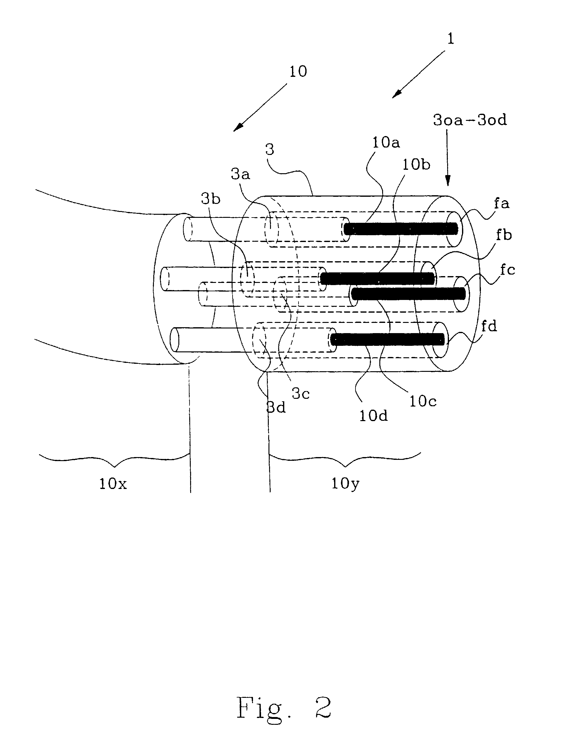
The present invention relates to a device (1) that can be used to connect a cable (10). The connector includes a contact matrix (3) and the cable includes electrical conductors (10a-10d). The matrix elements of the contact matrix (3through-passing channels (3a-3d) in which the conductors (10a-10d) have been placed and the ends of said conductors applied to the outlet ends (3oa-3od) of the channels. The conductor ends are each applied electrically to a contact receiving device through the medium of an electrically conductive and elastically resilient material.

Description

[0001] The present invention relates to a cable connecting device, and to a system that includes such a cable connecting device. The invention also relates to a method of fitting the cable to the connector.DESCRIPTION OF THE BACKGROUND ART[0002] Electronic devices tend to become smaller and smaller in volume, at the same time as system solutions become successively larger. Large system solutions involve many cable connections, which means that the cable connections to said devices are also required to be of smaller size. Fibre optics is a solution that permits high signal transmission with only a few connections. One drawback with fibre optics, however, is that a Fibre optic transmission requires a laser to be used as a signal generator. A laser incurs a high cost and, moreover, has low efficiency since a large amount of the energy required by the laser is converted to heat. The problem is less pronounced in the case of conventional electric signal transmission. U.S. Pat. No. 5,947,...

Claims


Application Information

Patent Timeline
IPC IPC(8): H01R9/03H01R9/05H01R33/76
CPCH01R9/032H01R33/7635H01R9/0506H01R13/65912
Inventor SIEBERT, WOLFGANG PETER
Owner TELEFON AB LM ERICSSON (PUBL)
Learn More