Transformer
a transformer and transformer technology, applied in the direction of transformer/inductance details, basic electric elements, coils, etc., can solve the problems of difficult to ensure a predetermined creepage distance between the primary and secondary windings, and difficult to meet the safety standard of transformers
- Summary
- Abstract
- Description
- Claims
- Application Information
AI Technical Summary
Benefits of technology
Problems solved by technology
Method used
Image

Examples
first embodiment
[0059] First Embodiment
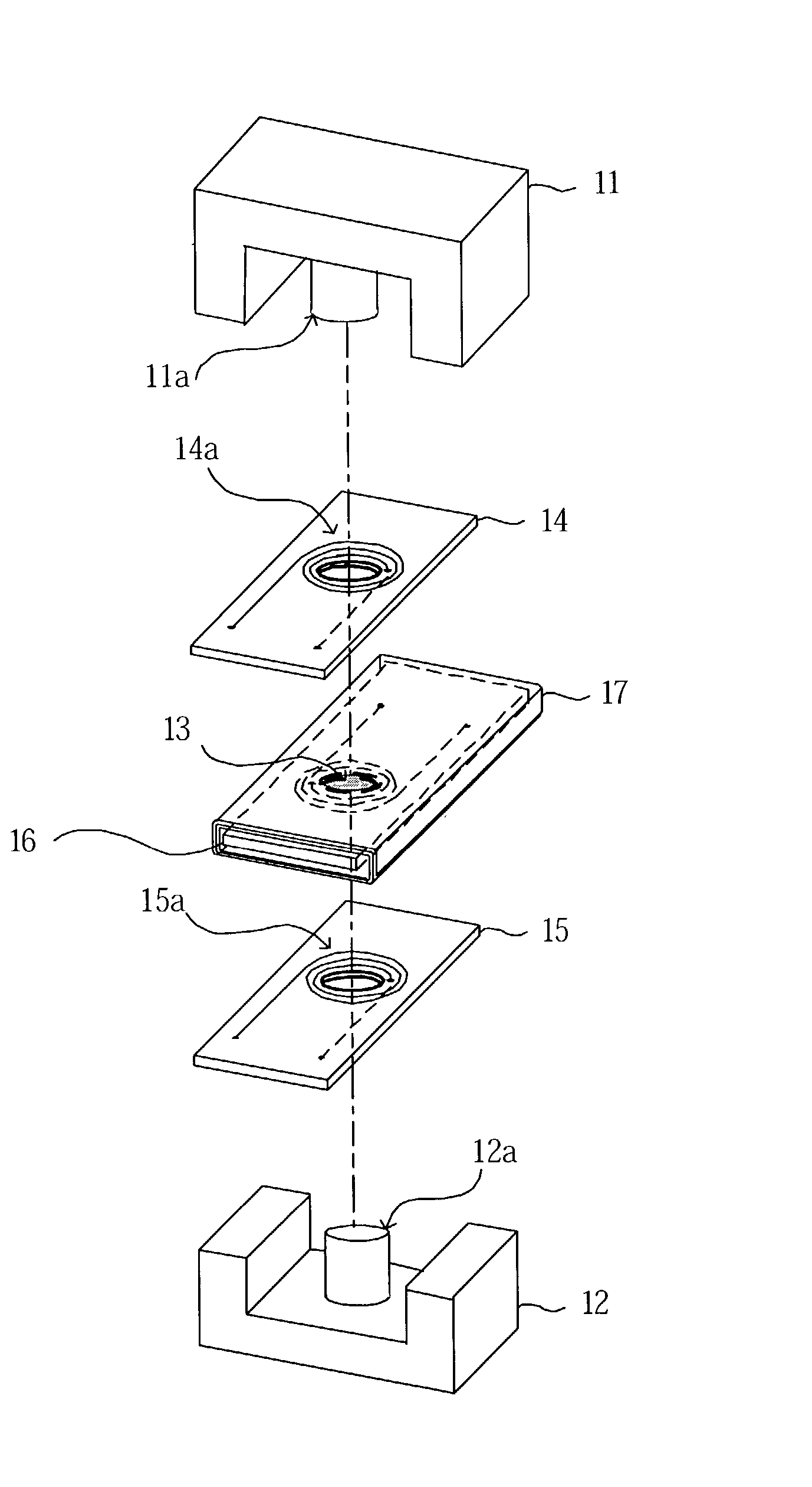
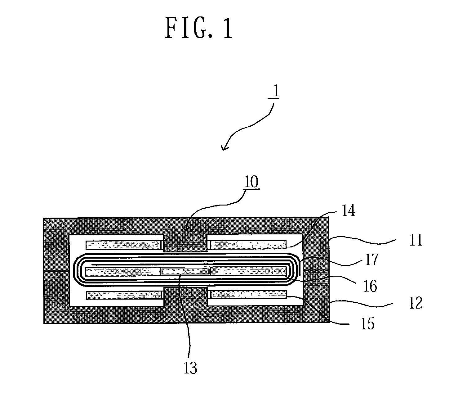
[0060] A transformer according to the first embodiment of the present invention comprises, as shown in FIG. 1, a core 10, first substrates 14 and 15, a second substrate 16 and an insulating sheet 17.
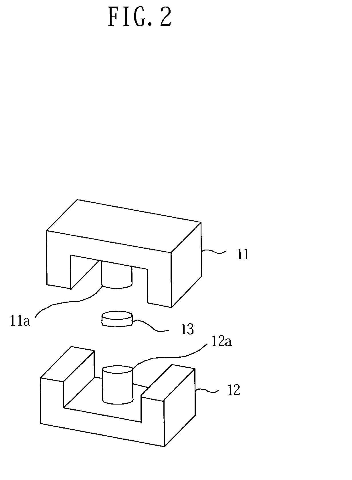
[0061] The core 10 is formed from magnetic materials, such as silicon steel sheet, ferrite, etc., and comprises E-type core parts 11 and 12 and a cylindrical core part 13, as shown in FIGS. 1 and 2.
[0062] Each of the E-type core parts 11 and 12 is formed in an "E" shape in its side view, has a rectangular cross section, and includes cylindrical core legs 11a and 12a in the center thereof. The cylindrical core part 13 has approximately the same thickness (height) as that of the second substrate 16 and approximately the same diameter as that of the core legs 11a and 12a.
[0063] The second substrate 16 is formed from an insulation substrate, and includes a penetration (insertion) hole 16a in the center thereof, as shown in FIGS. 3A and 3B. This penetration (insertion) ...
second embodiment
[0081] Second Embodiment
[0082] In the first embodiment, the cylindrical core part 13 is arranged between the core legs 11 and 12a. However, in the case where the magnetic resistance of the core 10 is set high, the cylindrical core part 13 may not be arranged between the core legs 11a and 12a, as illustrated in FIG. 7.
[0083] In this case, a part of the magnetic path is formed by a gap between the core legs 11a and 12a of the E-type core parts 11 and 12.
[0084] According to such a structure, magnetic saturation is unlikely to occur in the transformer 1 of the second embodiment as compared to the transformer 1 of the first embodiment.
[0085] It is not necessary that the penetration (insertion) hole 16a be arranged in the second substrate 16, because the cylindrical core part 13 is not used. In this case, a portion of the substrates between the core legs 11a and 12a serves as a gap. Further, a spacer which is formed of a resin, etc. may be arranged in the penetration (insertion) hole 16a ...
third embodiment
[0086] Third Embodiment
[0087] The third embodiment of a switching source (power supply) circuit, which includes the transformer 1 according to the first or second embodiment mounted on a circuit substrate thereof, will now be described.
[0088] The switching source circuit according to the third embodiment of the present invention includes a circuit substrate 36, as shown in FIG. 8. A switching circuit, a rectification circuit, and a smoothing circuit, etc. are arranged in a circuit arrangement section A1 on the circuit substrate 36. The transformer 1 is arranged in a transformer arrangement section A2, which is a predetermined distance away from the circuit arrangement section A1. The circuit arrangement section A1 and the transformer arrangement section A2 form a DC-DC converter as a whole.
[0089] The switching circuit formed in the circuit arrangement section A1 includes an IC (Integrated Circuit) 31 for switching, a FET (Field Effect Transistor) 32, an oscillator and the like, and ...
PUM
| Property | Measurement | Unit |
|---|---|---|
| voltage | aaaaa | aaaaa |
| thickness | aaaaa | aaaaa |
| insulating | aaaaa | aaaaa |
Abstract
Description
Claims
Application Information
 - R&D
- Intellectual Property
- Life Sciences
- Materials
- Tech Scout
- Unparalleled Data Quality
- Higher Quality Content
- 60% Fewer Hallucinations
Browse by: Latest US Patents, China's latest patents, Technical Efficacy Thesaurus, Application Domain, Technology Topic, Popular Technical Reports.
© 2025 PatSnap. All rights reserved.Legal|Privacy policy|Modern Slavery Act Transparency Statement|Sitemap|About US| Contact US: help@patsnap.com