Method for verifying the tightness of a tank system in a motor vehicle

a technology for tightness testing and motor vehicles, applied in the direction of fluid tightness measurement, combustion air/fuel air treatment, instruments, etc., can solve the problems of inability to reliably decide in this manner, and failure to achieve fault outpu

Inactive Publication Date: 2002-10-31
ROBERT BOSCH GMBH
View PDF0 Cites 5 Cited by
  • Summary
  • Abstract
  • Description
  • Claims
  • Application Information

AI Technical Summary

Problems solved by technology

A reliable decision is therefore not possible in this manner as to whether a large is leak is present having a diameter of 1 mm or more.
On the other hand, for other tolerances, a pregiven current threshold can be reached also for a leak having a diameter of more than 1 mm in a time interval, which is less than a pregiven diagnostic time interval and this would lead to the situation that a fault output would not take place.

Method used


Image

  • Method for verifying the tightness of a tank system in a motor vehicle
  • Method for verifying the tightness of a tank system in a motor vehicle
  • Method for verifying the tightness of a tank system in a motor vehicle

Examples


Embodiment Construction

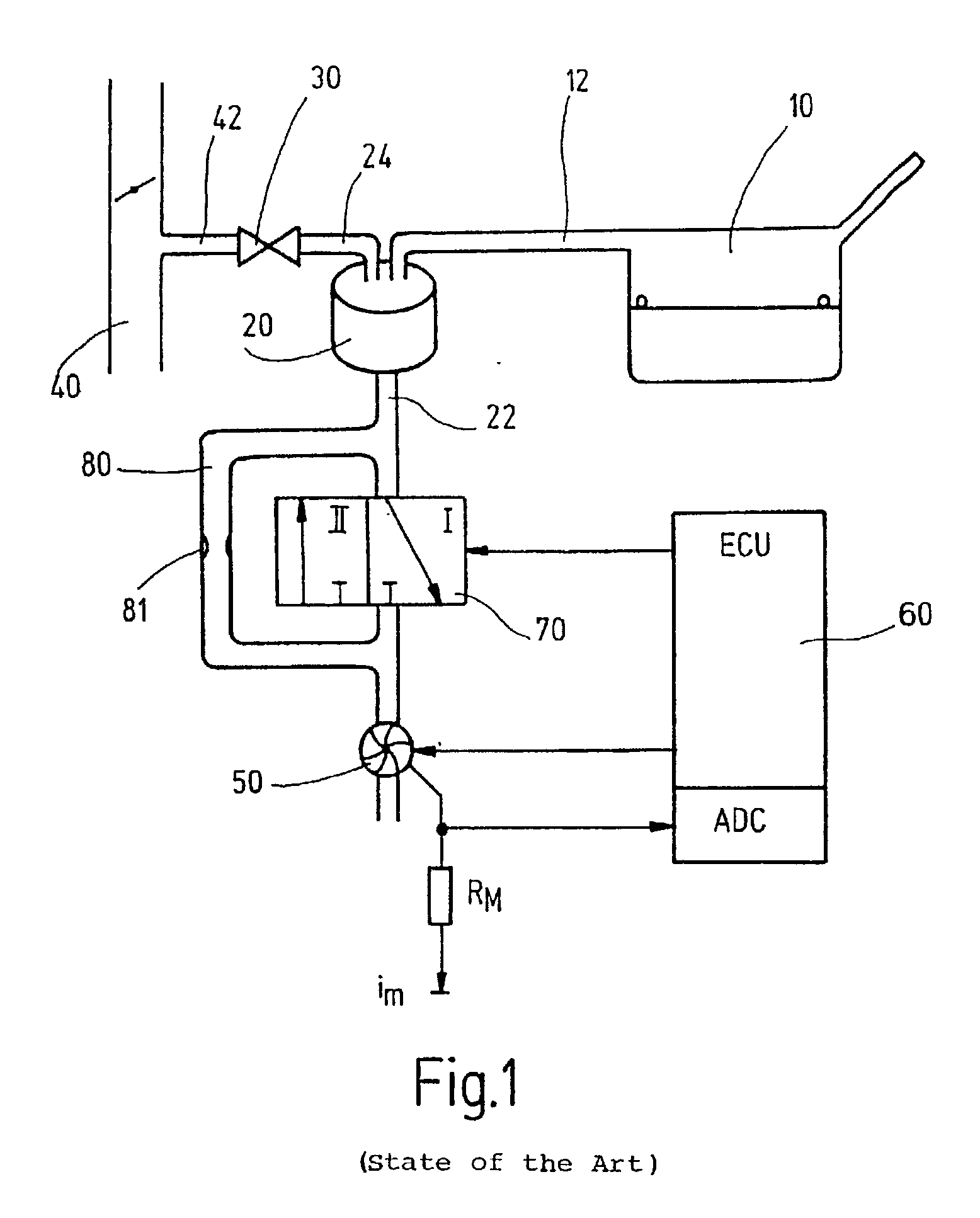
[0021] The invention is described in the following with respect to an example of a tank-venting system of a motor vehicle. It is, however, understood that the method of the invention can be used not only for a tank-venting system but for any desired tank system.

[0022] A tank-venting system of a motor vehicle tank system is shown in FIG. 1 and includes a tank 10, an adsorption filter 20 (for example, an active charcoal filter), a venting line 22 connectable to the ambient and a tank-venting valve 30. The adsorption filter 20 is connected to the tank 10 via a tank connecting line 12. The tank-venting valve 30 is connected, on the one hand, to the adsorption filter 20 via a valve line 24 and, on the other hand, to an intake manifold 40 of an internal combustion engine (not shown) via a valve line 42.

[0023] Hydrocarbons develop in the tank 10 because of vaporization and these hydrocarbons deposit on the adsorption filter 20. To regenerate the adsorption filter 20, the tank-venting valve...


PUM


Abstract

A method for checking the tightness of a tank system, especially of a tank-venting system of a vehicle, wherein an overpressure or an underpressure relative to the atmospheric pressure is introduced into the tank system by means of a pressure source and the time-dependent trace of at least one operating characteristic variable of the pressure source is detected when introducing the overpressure/underpressure up to reaching a first time point or a first pressure level and is compared to a time-dependent trace of the operating characteristic value up to this time point or up to this pressure level (expected diagnostic trace), the time-dependent trace being expected in the case of a tight tank system, and, a conclusion as to non-tightness is drawn when the detected time-dependent trace deviates from the expected diagnostic trace by at least a pregiven value, characterized in that, when a deviation is determined, the overpressure/underpressure in the tank-venting system is further increased up to reaching a second time point or a second pressure level; the operating characteristic value of the pressure source continues to be detected and compared to an expected further time-dependent trace of the operating variable in the case of a tight system (further diagnostic trace) and, a fault announcement is only then outputted when the detected time-dependent trace during the introduction of the further overpressure/underpressure deviates from the further diagnostic trace.

Description

STATE OF THE ART[0001] The invention relates to a method for checking the tightness of a tank system, especially a tank-venting system, in accordance with the preamble of claim 1.[0002] A method for checking the tightness of the tank-venting system of a vehicle is disclosed, for example, in DE 198 09 384 A1 as well as in DE 196 36 431 A1.[0003] In the above, an overpressure is introduced into a tank-venting system by means of a pressure source and the time-dependent trace of at least one operating characteristic variable of the pressure source is detected while introducing the overpressure. This time-dependent trace is compared to a time-dependent trace of the operating characteristic variable (diagnostic trace), which is expected in the case of a tight tank system. This expected time-dependent trace is, for example, previously measured, computed or estimated. A conclusion is then drawn as to non-tightness when the detected time-dependent trace deviates from the diagnostic trace by ...

Claims


Application Information

Patent Timeline
Patent Type & Authority Applications(United States)
IPC IPC(8): G01M3/26F02M25/08F02M37/00G01M3/32
CPCG01M3/32F02M25/0818
Inventor STREIB, MARTIN
Owner ROBERT BOSCH GMBH
Why Eureka
Try Eureka