
Apparatus for and method of installing subsea components

a technology for installing subsea components and accessories, which is applied in the field of accessories for and methods of installing subsea components, can solve the problems of ahts vessels, ahts-type vessels, and the cost of using derreks and crane barges can be as much as 3 to 10 times more expensive per day, so as to reduce the potential for components to bounce and reduce the effect of heaving

Inactive Publication Date: 2002-09-19
AKER MARINE CONTRACTORS
View PDF0 Cites 32 Cited by
  • Summary
  • Abstract
  • Description
  • Claims
  • Application Information

AI Technical Summary

Benefits of technology

[0013] The motion compensator acts to reduce the effect of heave on the component as it lowered to the seafloor and thus, reduces the potential for the component to bounce up and down on the floor. The spreader beam separates the lowering wire and assists in controlling component orientation. Use of the A-frame avoids overboarding the component as it is deployed into the water.

Problems solved by technology

While derreck and crane barges are frequently used all around the world to install heavy components, use of these vessels is typically much more expensive than the AHTS-type vessels or work boats.
Indeed, in recent years the cost of using a derreck and crane barges may be as much as 3 to 10 times more expensive per day in comparison to the relatively smaller AHTS vessel.
Hence, the major drawback to using larger vessels to install the same components is cost.
Notwithstanding, while the AHTS vessel is more cost efficient, there are problems associated with lowering subsea components from the floating platform of this vessel that crane and / or derreck barges do not suffer.
On the other hand, both derricks and AHTS vessels require relatively complicated procedures in order to ensure the component clears the vessel.
Another problem is the relative motion between the component and the sea bed prior to touch down.
Heave in particular can cause damage to the component and other structures around it, if it is moving up and down uncontrollably.
A further problem is the twisting of the component and torque on the lowering wire prior to touch down.
Excessive twisting may also cause damage to the lowering lines.
Steel wires typically have tension-induced torque characteristics, which can increase the chance of twisting.
Unfortunately, even in light of the novel and useful nature of these methods, certain problems still persist.
For example, for deep subsea installation, direction control remains a problem when installing components through the use of the method and apparatus described in U.S. Pat. No. 6,009,825.
An example of torque balanced wire is multistrand or multilayer strand, difficult to handle, fragile and expensive.
Overboarding remains a problem when only winches are used as shown in U.S. Pat. No. 6,122,847.
Moreover, control over the torque or twist of the component is missing unless a second vessel is used.
Furthermore, as taught in U.S. patent application Ser. No. 09 / 627,873 while installation of components using a single vessel is preferred, the method described lacks the ability to control the torque on the component and is not suitable for deep sea installations particularly where the environment is harsh and / or the relative motion between the component and the sea floor maybe uncontrollable.

Method used


Image

  • Apparatus for and method of installing subsea components
  • Apparatus for and method of installing subsea components
  • Apparatus for and method of installing subsea components

Examples


example 1

[0044] The vessel 10 is an AHTS of at least 90 meters long, 23,480 BHP of main engine power and continuous bollard pull of 250 tons and having the following characteristics:

[0045] LOA=90.30 meters, Beam=23.00 meters, Depth=9.50 meters;

[0046] 17280 kW (23480 BHP) main propulsion engines;

[0047] 2.times.880 kW stern thrusters, 1.times.1500 kW bow thruster and 1.times.1300 kW retractable azimuth type bow thruster;

[0048] DP (AA) under Lloyd's Class (DP Class II);

[0049] Triple drum anchor handling & towing winch, maximum pull capacity 400 tonnes and 625 tons depending on drum.

[0050] 2 chain handling systems and 4.times.250 cubic meter chain lockers;

[0051] 2 sets of 700 tons shark jaws with towing / guide pins;

[0052] Two 4.0 meters diameter stern rollers, rated at 800 tons each;

[0053] 60 person accommodations; and

[0054] Two complete 100 hp ROV systems, one of which will be the back-up system. The ROV systems are mounted on separate platforms above the vessel's main deck.

[0055] The capacity o...

example 2

[0072] In order to theoretically calculate nitrogen pressure before starting operation when motion compensator is filly retracted, the below procedure can be followed:

[0073] 1. Determine the weight of load into water.

[0074] 2. Draw the isothermic curve from the central point

[0075] X=2 m

[0076] Y=above load

[0077] Calculate the corresponding POVO at X=0 m (retracted position)

P.sub.0V.sub.0=P.sub.1V.sub.1.times.P.sub.2V.sub.2

[0078] When

[0079] V.sub.0=Nitrogen Volume when fully retracted

[0080] =3.times.353+640=1700 liters

[0081] V.sub.1=Nitrogen Volume when mi-extended

[0082] =3.times.353+320=1380 liters

[0083] P.sub.1=Pressure at mid-extended

[0084] =Load / 1.583

[0085] V.sub.2=Nitrogen Volume when fully extended

[0086] =3.times.353=1060 liters

[0087] P.sub.0 is the Nitrogen pressure when fully retracted.

[0088] 3. Draw the adiabatic curves using the above procedure but with a polytropic exponent n=1.4

P.sub.0V.sub.0.sup.1.4=P.sub.1V.sub.1.sup.1.4=P.V..sup.1.4

[0089] Nitrogen Pressure Selection

2 In...

example 3

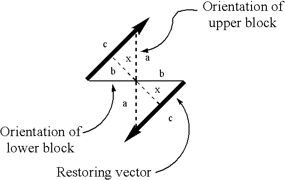
[0094] Torque values generally quoted are maximum values and are given at a load equal to 20% of the breaking strength (FOS=5). Some ropes will have non-linear torque to load curves. It is generally assumed that the rope is torque-free when unloaded. Torque is maximum on a new rope. Wear and usage diminishes the torque value, improving stability. These calculations may be conservative in other ways.

[0095] For example, if the increase in load is due to the weight of the wire, the incremental increase in rotation should be half the value that would be caused by increasing the component's 22 weight by the same amount.

[0096] Weight of manifold: W:=927.multidot.kip

[0097] Should include wire and spreader beam too. Term cancels out later in analysis.

[0098] Nominal rope diameter: d:=3.multidot.in

[0099] Number of parts: n:=2

[0100] Torque generated per part of sheave line: 1 T part := T fac 1 W n d T part = 8111.25 lb ft

[0101] Total torque generate by two-parts, an upper block or T.sub.tot:=n...


PUM


Abstract

An apparatus for installing subsea components includes the use of a motion compensator to counterbalance and offset load on the component and lowering wire caused by movement of the vessel as a result of waves and wind.

Description

BACKGROUND OF THE INVENTION[0001] To install heavy subsea components into the seafloor, a floating installation vessel is typically employed. Since the components lowered vary in weight from several tons to 200 tons or more, installation vessels such as a barge commonly utilize a crane or a derreck. Other vessels have a semi-submersible hull where the component may be lowered through an aperture in the hull ("moonpool") into the water and down to the seabed. To perform such operation with this vessel, a crane or derreck is used depending on the component. For example, a crane will lower a wet block or steel wire while the derreck lowers the drill string.[0002] More recently, Anchor Handling Tug and Supply ("AHTS") vessels are used to install heavy subsea equipment. These vessels have a relatively small ship-like hull, and often do not use a crane but rather use winches to lower components into the sea. The AHTS vessel has less capacity in load, storage and accommodation than a typic...

Claims


Application Information

Patent Timeline
IPC IPC(8): B63B21/16B63B21/22B63B27/36B63B35/00B66C13/02
CPCB63B21/16B63B21/22B63B35/003B66C13/02B63B27/08B63B27/10
Inventor HAGEN, DAGFINNHVAM, LARS RAABEBURLEY, RODTREU, JOHANNES JACOBUS
Owner AKER MARINE CONTRACTORS
Learn More