Composite high frequency component and mobile communication apparatus including the same
a high frequency component and mobile communication technology, applied in electrical devices, multi-band filters, substation equipment, etc., can solve the problems of increased insertion loss, voluminous circuit substrates, and large occupied area of high frequency switches, so as to reduce the loss, improve the insertion loss due to the wiring between the elements, and improve the insertion loss due to the strip-line electrode
- Summary
- Abstract
- Description
- Claims
- Application Information
AI Technical Summary
Benefits of technology
Problems solved by technology
Method used
Image
Examples
first embodiment
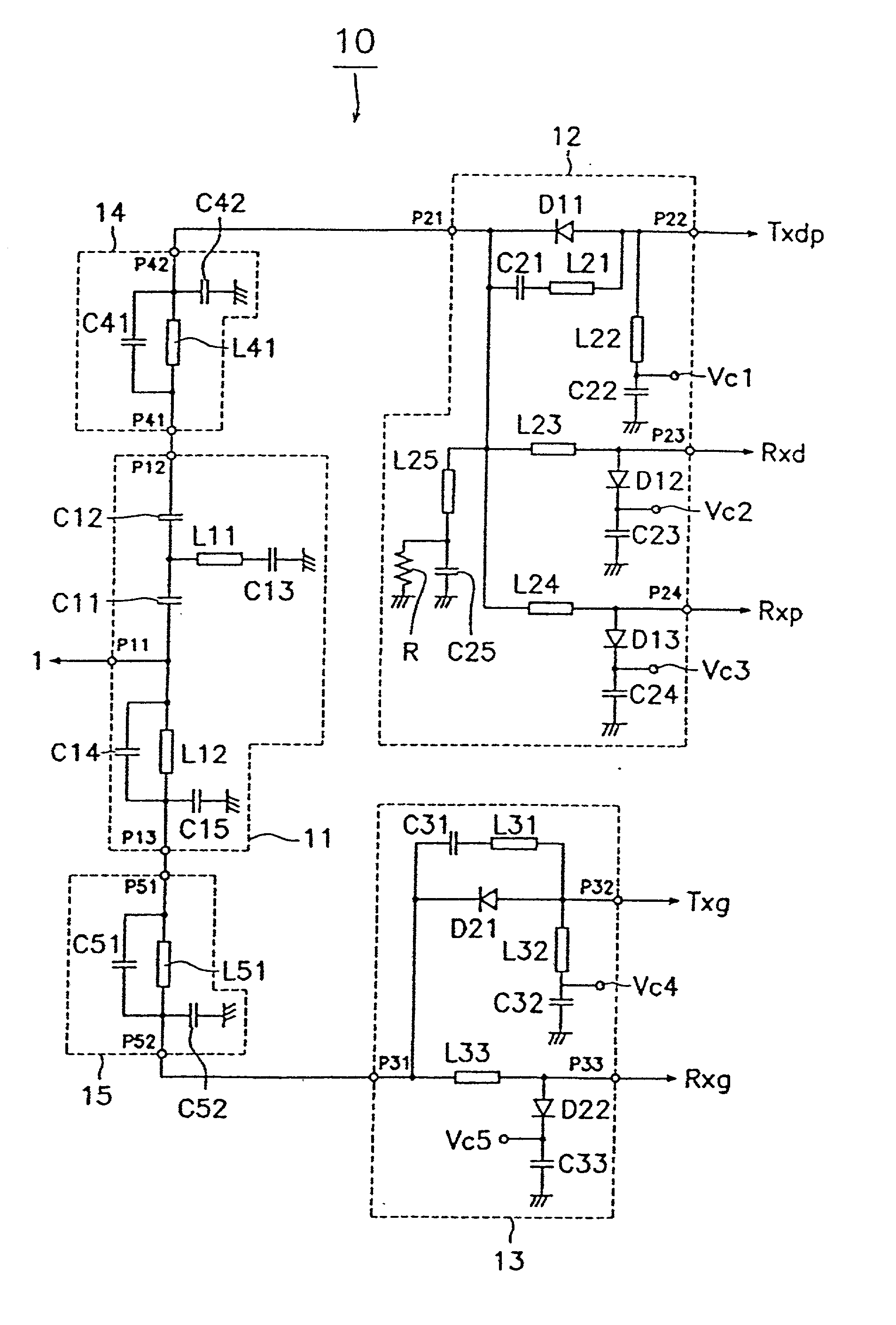
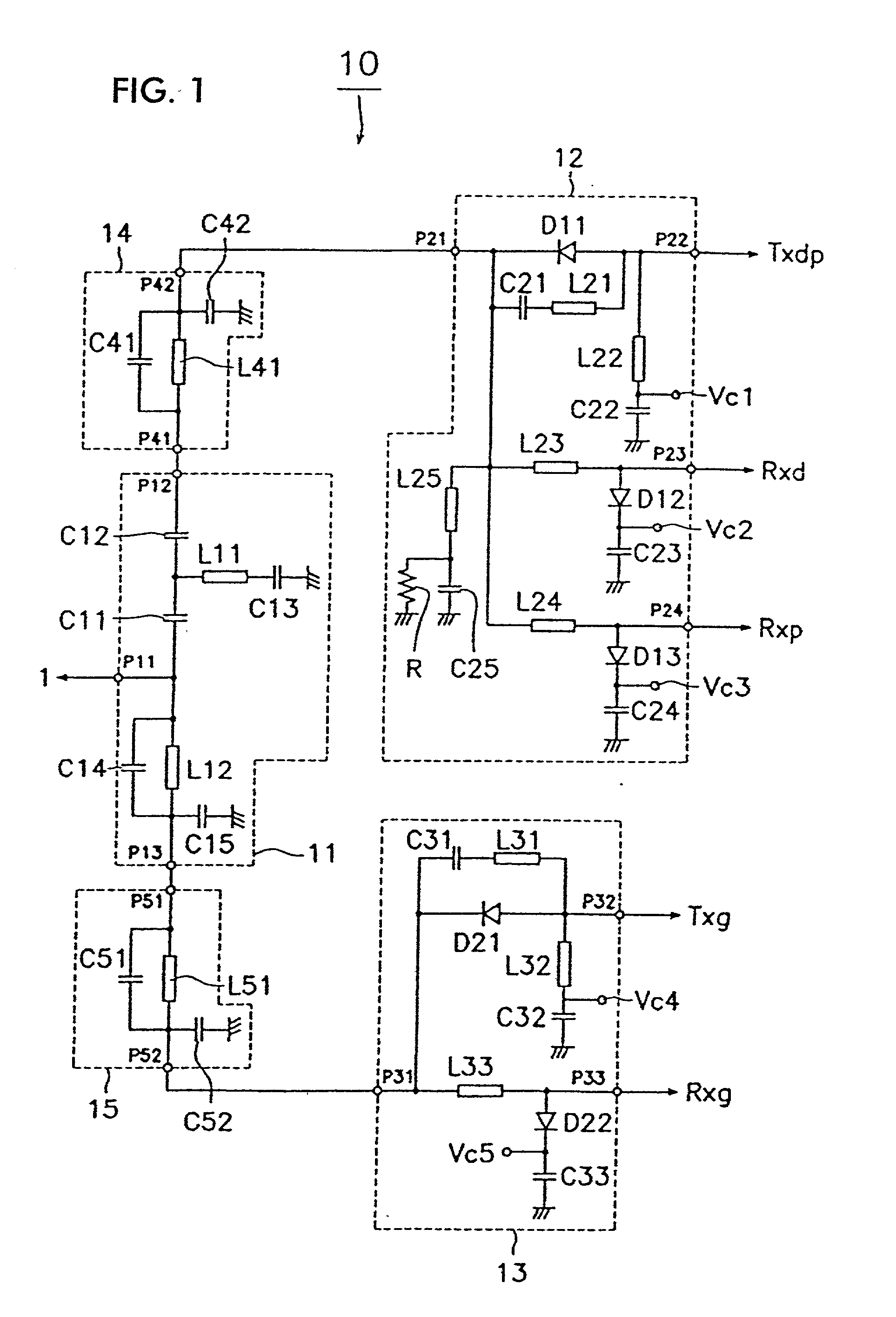
[0037] FIG. 1 is a circuit diagram of a composite high frequency component according to the present invention. A composite high frequency component 10, which constitutes partially a front end portion corresponding to a first, second, and third communication system, namely, DCS (1.8 GHz band), PCS (1.8 GHz band), and GSM (900 MHz band). The front end portion is composed of a diplexer 11, a first high frequency switch 12 having four ports, a second high frequency switch 13 having three ports, and first and second filters 14 and 15.
[0038] An antenna 1 is connected to the first port P11 of diplexer 11. The first port P41 of first filter 14 is connected to the second port P12 of diplexer 11, and the first port P51 of second filter 15 is connected to the third port P13 of diplexer 11.
[0039] The first port P21 of first high frequency switch 12 is connected to the second port P42 of the first filter 14. The transmitting section Txdp common to DCS and PCS is connected to the second port P22 ...
second embodiment
[0080] FIG. 3 is a circuit diagram of the composite high frequency component according to the present invention. The composite high frequency component 20 is composed of a diplexer 11, first and second high frequency switches 12 and 13, and first and second filters 14 and 15.
[0081] The arrangements of the diplexer 11 and the first and second filters 14 and 15 are the same as those in the composite high frequency component 10 of the first embodiment shown in FIG. 1. Their detailed description will be omitted.
[0082] The first high frequency switch 12 is composed of the first diodes D11 through D13 which are first switching elements, the second inductors L21 through L25 which are second inductance elements, and the second capacitors C21 through C25 which are second capacitance elements.
[0083] The first diode D11 is connected between the first port P21 and the second port P22 such that its cathode is at the first port P21. A series circuit comprising the second inductor L21 and the seco...
third embodiment
[0105] In the above-described composite high frequency component of the third embodiment, each filter is arranged in the post-stage or on the transmitting section side of the high frequency switch, i.e., between the high frequency switch and the transmitting section. Thus, in transmission, distortions in high-power amplifiers provided in the transmitting sections can be reduced by means of the filters, respectively. Thus, an insertion loss on the receiving side can be improved.
[0106] FIG. 5 is a block diagram showing a part of the configuration of a triple band portable telephone (a type of mobile communication apparatus) and illustrates, as an example, a combination of DCS and PCS operative in the 1.8 GHz band and GSM in the 900 MHz band. The triple band portable telephone 40 is provided with the antenna 1 and the composite high frequency component 10 (FIG. 1).
[0107] The antenna 1 is connected to port P11 of the composite high frequency component 10. Ports P22, P23, P24, P32, and P...
PUM
 Abstract
Description
Claims
Application Information
 - R&D
- Intellectual Property
- Life Sciences
- Materials
- Tech Scout
- Unparalleled Data Quality
- Higher Quality Content
- 60% Fewer Hallucinations
Browse by: Latest US Patents, China's latest patents, Technical Efficacy Thesaurus, Application Domain, Technology Topic, Popular Technical Reports.
© 2025 PatSnap. All rights reserved.Legal|Privacy policy|Modern Slavery Act Transparency Statement|Sitemap|About US| Contact US: help@patsnap.com


