Electrical connector assembly having improved guiding means

a technology of guiding means and connectors, which is applied in the direction of coupling device connections, printed circuit aspects, coupling device details, etc., can solve the problems of reducing the manufacturing cost of connectors, affecting the service life of connectors, and requiring the dumping of substrates and contacts,

Inactive Publication Date: 2002-09-12
HON HAI PRECISION IND CO LTD
View PDF0 Cites 48 Cited by
  • Summary
  • Abstract
  • Description
  • Claims
  • Application Information

AI Technical Summary

Benefits of technology

0015] The guiding means includes a pair of frames, which define a chamber between each frame and an outmost lead-in bar of the first housing portion, at opposite ends of the first housing portion and a pair of guiding posts at opposite ends of the dielectric member. The guiding posts are received in corresponding chambers before the first housing portion engages with the dielectric member for guidin

Problems solved by technology

The SMT requires expensive machine, thereby increasing the manufacturing cost of the connectors.
Second, when the substrates, which are originally designed for signal transmission are required to be replaced by substrates for power transmission, the substrates together with the contacts must be discarded.
Third, there is no means for guiding contacts of a mating connector to engage with the mating surface of the substrates.
Ther

Method used


Image

  • Electrical connector assembly having improved guiding means
  • Electrical connector assembly having improved guiding means
  • Electrical connector assembly having improved guiding means

Examples


Embodiment Construction

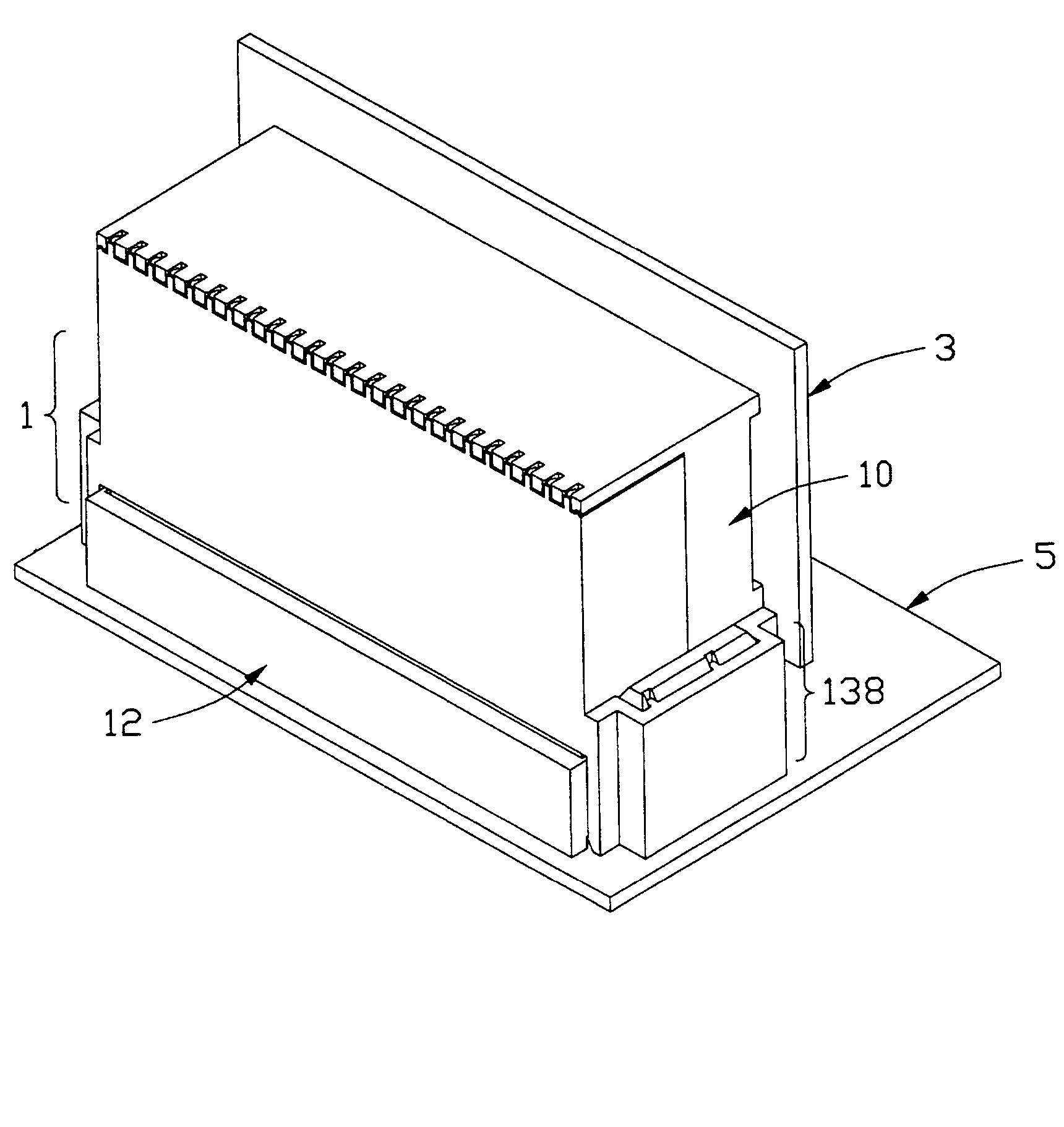
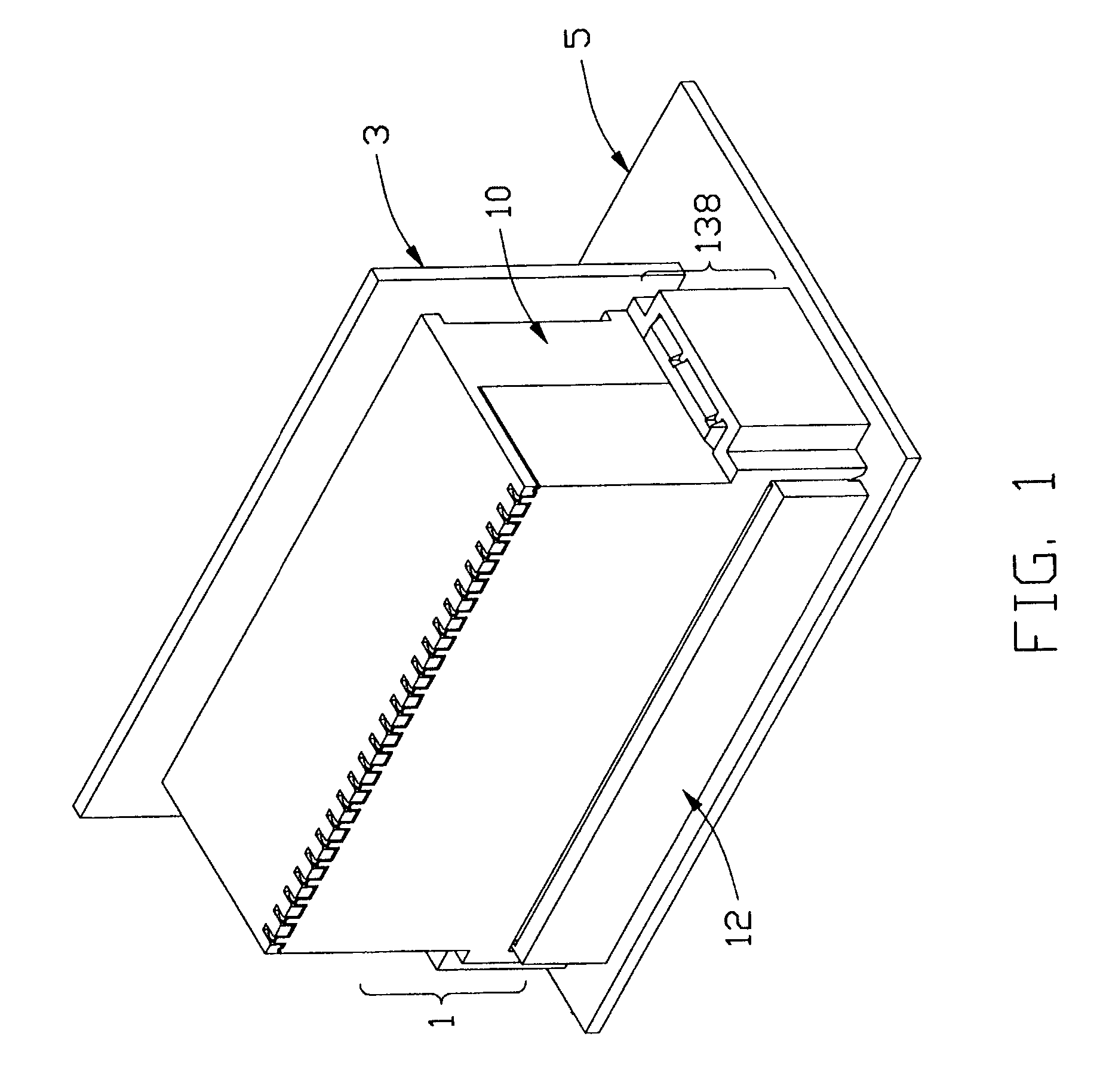
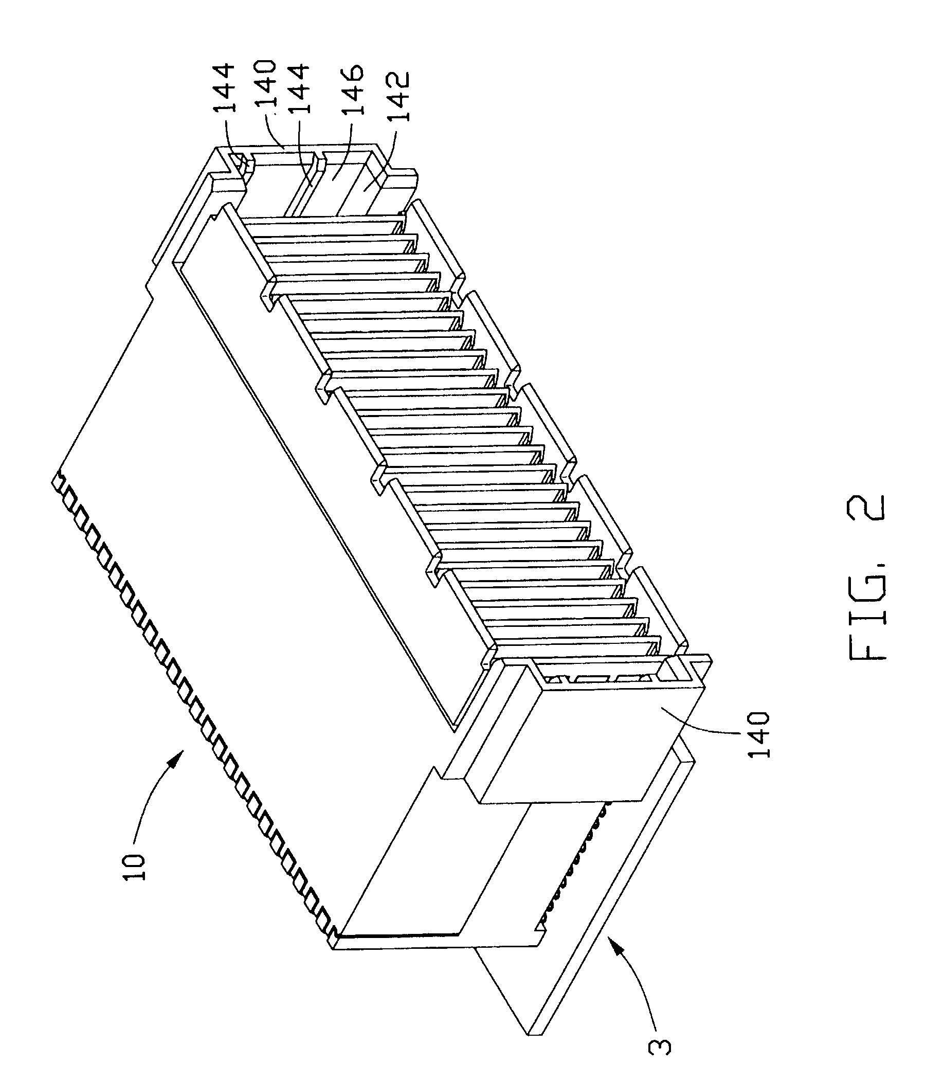
[0031] Referring to FIGS. 1-3, 6A-8B and 10, an electrical connector assembly 1 of the present invention includes a male connector 10 mounted on a first printed circuit board (PCB) 3 and a female connector 12 mounted on a second PCB 5. The male connector 10 includes an insulative housing 14, a plurality of substrates 16 and a plurality of signal contacts 18 and grounding terminals 20 received in the housing 14. The female connector 12 includes an insulative housing 22, a plurality of signal contacts 24 and grounding terminals 26 received in the housing 22.

[0032] Referring to FIGS. 3-9, the housing 14 includes first and second individual housing portions 28, 30 engageable with each other. The first housing portion 28 has a front surface 32 for mating with the female connector 12, a rear surface 34 and a lower surface 36 in orthogonal with the rear surface 34. The first housing portion 28 defines a plurality of passageways 38 through the rear surface 34, the lower surface 36 and termi...


PUM


Abstract

A male connector (10) includes first and second individual housing portions (28, 30) engaging with each other, a number of substrates (16) held by the first housing portion and a number of signal contacts (18) and a number of grounding terminals (20) held by the second housing portion with the signal contacts confronting the grounding terminals. Each substrate has a first edge (108) and a second edge (110) orthogonal with the first edge. The first edges of the substrates are hidden behind corresponding lead-in bars (44) of the first housing portion and the second edges of the substrates are sandwiched between and removeably held by the signal contacts and the grounding terminals. The second edges are pushed toward the signal contacts by the grounding terminals because the grounding terminals are stronger than the signal contacts. A female connector (12) mateable with the male connector includes a dielectric member (22) and a number of signal contacts (24) and a number of grounding terminals (26) retained in the dielectric member in face-to-face relationship. The signal contacts straddle on a bottom surface (128) of the dielectric member. The male and the female connectors have a guiding means for guiding the connectors to correctly mate with each other.

Description

CROSS-REFERENCES TO RELATED APPLICATIONS[0001] This patent application is a continued-in-part (CIP) application of patent application Ser. No. 09 / 746,088, filed on Dec. 21, 2000, and a Co-pending Application of Patent Application with an unknown serial number, entitled "ELECTRICAL CONNECTOR HAVING IMPROVED GROUNDING TERMINALS", invented by the same inventors as this patent application, another co-pending application of application with an unknown serial number, entitled "ELECTRICAL CONNECTOR HAVING PRINTED SUBSTRATES THEREIN ELECTRICALLY CONTACTING CONDUCTIVE CONTACTS THEREOF BY SOLDERLESS", invented by the same inventors as this patent application; and another co-pending application with an unknown serial number, entitled "ELECTRICAL CONNECTOR HAVING IMPROVED CONTACTS", invented by Timothy Brain Billman, all assigned to the same assignee and filed on the same date with this application. U.S. Pat. No. 6,375,508 is also related hereto.BACKGROUND OF THE INVENTION[0002] 1. Field of the...

Claims


Application Information

Patent Timeline
IPC IPC(8): H01R13/514H01R13/516H01R13/631H05K1/11
CPCH01R13/514H01R13/516H01R13/631H01R23/6873H05K1/117H05K2201/2027H01R12/716H01R12/737H01R12/724H01R13/6587H01R13/6594
Inventor BILLMAN, TIMOTHY B.PICKLES, CHARLES S.
Owner HON HAI PRECISION IND CO LTD
Why Eureka
Try Eureka