Device for forming synthetic fiber materials

a technology of synthetic fibers and materials, applied in the field of synthetic fiber materials, can solve the problems of reducing the effectiveness of the manufacturing process, increasing the difficulty of further transportation through the melt line, and reducing the so as to reduce the quantity of heat energy required for heating the inner space, the distribution effect of the distributor plate is further improved, and the inner volume is reduced.

Inactive Publication Date: 2002-09-12
MICROFASER PRODNGMBH
View PDF0 Cites 0 Cited by
  • Summary
  • Abstract
  • Description
  • Claims
  • Application Information

AI Technical Summary

Benefits of technology

0016] The distribution effect of the distributor plate is further improved in that the surface of the distributor plate rises toward the rim and will ideally form a curved surface that is concave in the direction of the opening. In a preferred embodiment a truncated cone is positioned on the distributor plate; the diameter of this truncated cone is smaller than the diameter of the distributor plate. Here the diameter of the upper side of the distributor plate can correspond in terms of magnitude to the diameter of the opening of the feed opening.
0017] The continuously curved inner wall of the hollow reactor will ideally be parabolic in shape and will thus correspond to the surface that arises when a parabola is rotated around its own axis. Given the same height and the same diameter of the outlet opening, the continuous curve provides a considerably reduced inner volume compared to the known device, so that the quantity of heat energy required for heating the inner space is reduced. The invention design also minimizes the heat losses and the specific heat consumption.
0018] In a particularly preferred embodiment of the invention the inner wall forms a curved gap in conjunction with a container surrounding the hollow reactor, to which a steam feed and a steam outlet are attached. The continuous circulation of heated water vapor through the hollow space results in the uniform heating of the reactor walls. It is thus possible to produce the melt strip or the melt film at a uniform temperature and thickness, with the result that the fiber exhibits a uniform diameter over its entire length and has no unmelted parts. To this end it is expedient for the steam feed and the steam outlet to be positioned on the upper and lower rim of the inner wall. The steam can then be guided in the polymer melt's direction of flow, as well as in the opposite direction.

Problems solved by technology

The opened reactor basin results in an energy loss and diminishes the effectiveness of the manufacturing process.
Otherwise these channels become blocked with a mass of material that is not fully or melted, and this makes further transport through the melt lines more difficult.
The production of high-quality fibers from raw materials of lower quality is thus impossible.
In actual practice, however, a problem arises in that with conventional heating elements and a cylindrically shaped reactor it is impossible to uniformly heat the reactor wall and floor.
The formation of such standstill areas diminishes the productivity of the apparatus and has a negative effect on the fiber quality.
The result is that the fibers are formed unevenly, with thickened areas or inclusions of solid, unmelted pieces that vary in shape; the quality of the fibers is thus diminished.
If the reaction walls were heated to a greater degree this would lead to considerable overheating of the melt film.
Another disadvantage of the known device rests in the fact that more than 30% of the introduced heat energy is directly employed in heating the strip.
Furthermore, due to the back radiation between the heater and the reactor in the central part of the reactor the heating elements and the melt strip become overheated.
This may result in the heater being burned and to the partial or complete burnout of the polymer.
In this case, overheating and burning of the heating elements is also possible.

Method used


Image

  • Device for forming synthetic fiber materials
  • Device for forming synthetic fiber materials

Examples


Embodiment Construction

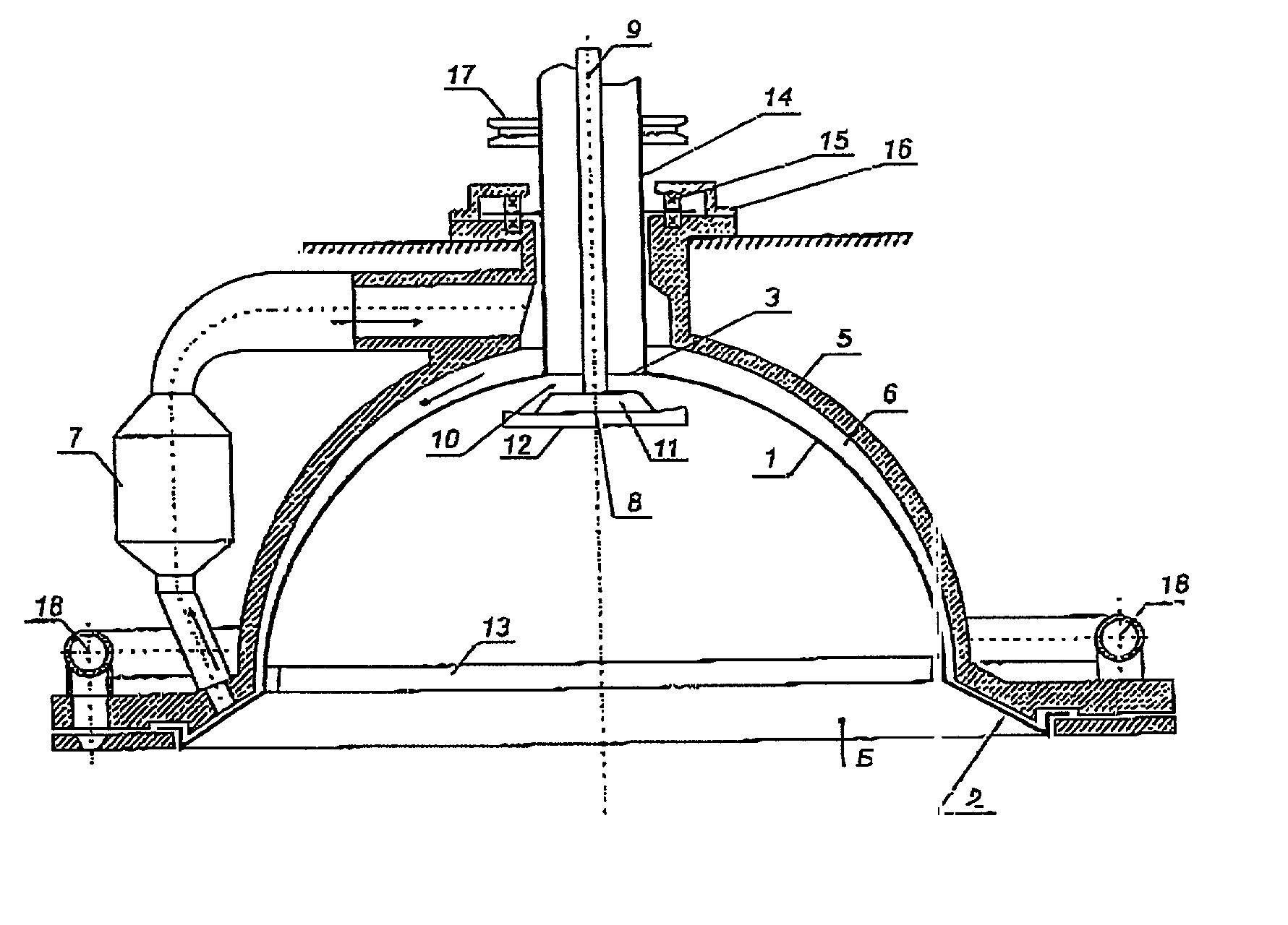
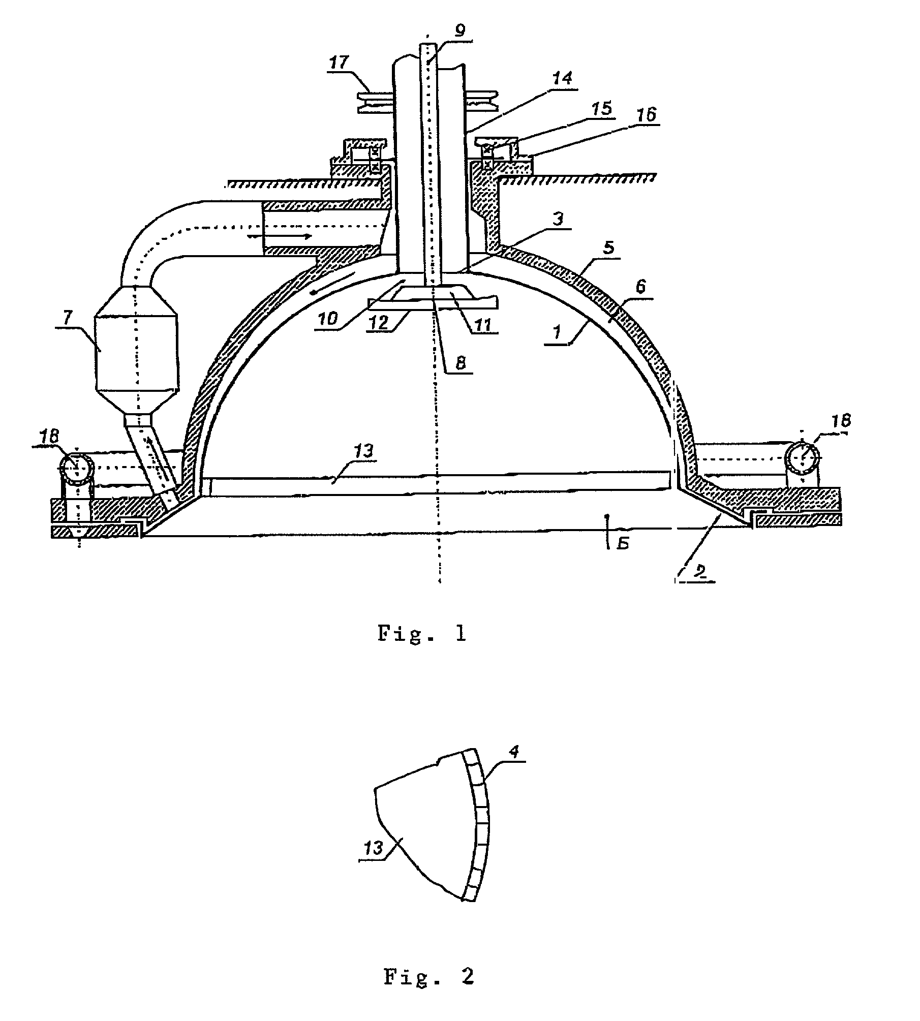
[0022] The device shown in the drawing serves to producer fibers from a thermoplastic melt and comprises a vertically installed rotating hollow reactor 1 in the form of a paraboloid, which is created by rotating a parabola around its own axis. Provided on the open rim of the paraboloid is a rim 2 that widens to form a cone. Centrally positioned in the curved portion of the paraboloid is an opening 3 for introducing a polymer melt. The inner wall of the hollow reactor 1 is provided with flat ribs 4, which run vertical to the rim 2 on the lower area of the hollow reactor 1.

[0023] The hollow reactor 1 is located in a container 5 that encloses it and whose surface accommodates the shape of the hollow reactor 1 in such a way as to produce a curved gap 6. The upper part of the gap 6 is connected to the outlet and the lower part of the gap 6 to the intake of a steam generator 7, with the result that a closed steam circuit is formed by the gap 6. The direction of movement of the water vapor...


PUM

PropertyMeasurementUnit
distanceaaaaaaaaaa
outer diameteraaaaaaaaaa
diameteraaaaaaaaaa

Abstract

Fibers of improved quality can be produced with a reduced energy input in a device for producing synthetic fiber materials which has a polymer melt feed leading to a rotating hollow reactor (1), the wall of which can be heated and which widens conically in order to guide a film melt toward an open side that can be closed with a lid (13), and which has ribs (4) for dividing the melt film into fibers that grow rigid after leaving the hollow reactor (1); and said improved quality call be achieved specifically in that the hollow reactor (1) is vertically oriented and exhibits a continuously curved inner wall and at the curved upper side exhibits an opening (3) for introducing the polymer melt, and in that a rotating distributor plate (12) is positioned opposite the opening (3), at a slight distance from the inner wall of the hollow reactor (1).

Description

BACKGROUND OF THE INVENTION[0001] 1. Field of the Invention[0002] The invention relates to a device for producing synthetic fiber materials, with a polymer melt feed leading to a rotating hollow reactor, the wall of which can be heated and which widens conically in order to guide a film melt toward an open side that can be closed with a lid, and with ribs for dividing the melt film into fibers that grow rigid after leaving the hollow reactor.[0003] 2. Background Description[0004] Synthetic fibrous materials with a polymer melt feed can be employed in particular as absorption agents that filter mineral oil and oil products, as well as a series of heavy metal ions, out of water. The process for manufacturing thermoplastic fibrous material usually involves two stages, namely the production of the melt and the formation of the fibers.[0005] In known facilities, the thermoplastic material is first melted and the melt is then extruded through spinnerets in order to form the fibers. An app...

Claims


Application Information

Patent Timeline
Patent Type & Authority Applications(United States)
IPC IPC(8): D01D5/08D01D5/18
CPCD01D5/08D01D5/18Y10S425/017
Inventor VOLOKITIN, GENNADYGAPEEV, VIKTORZOLOV, SERGUEY
Owner MICROFASER PRODNGMBH
Why Eureka
Try Eureka