Optical module and method of making the same
a technology of optical modules and optical beams, applied in the field of optical beams, can solve the problems of increasing the number of parts, increasing the manufacturing cost, and affecting so as to improve the wavelength stability of the laser beam, reduce the manufacturing cost and time, and reduce the size
- Summary
- Abstract
- Description
- Claims
- Application Information
AI Technical Summary
Benefits of technology
Problems solved by technology
Method used
Image
Examples
first embodiment
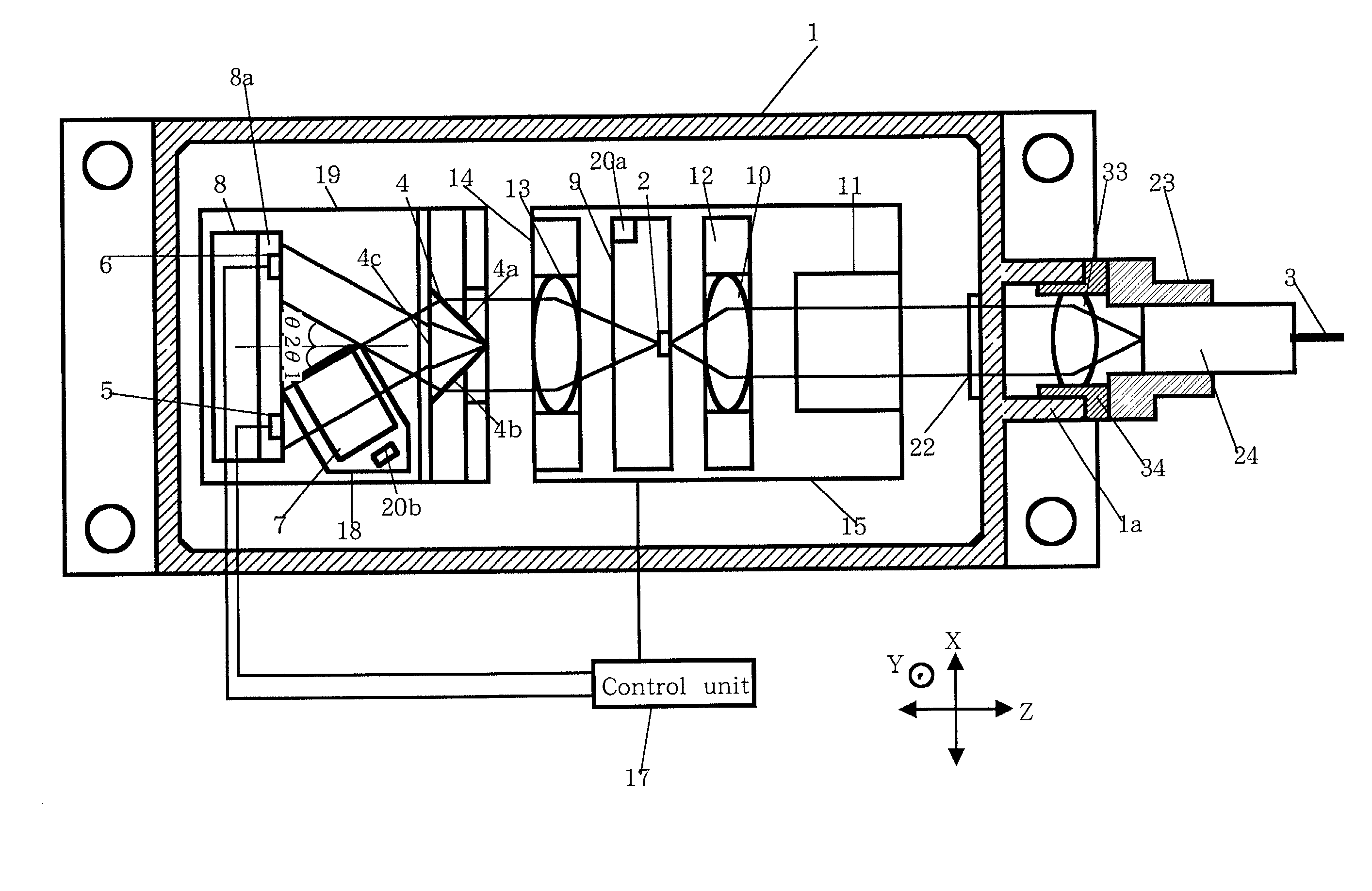
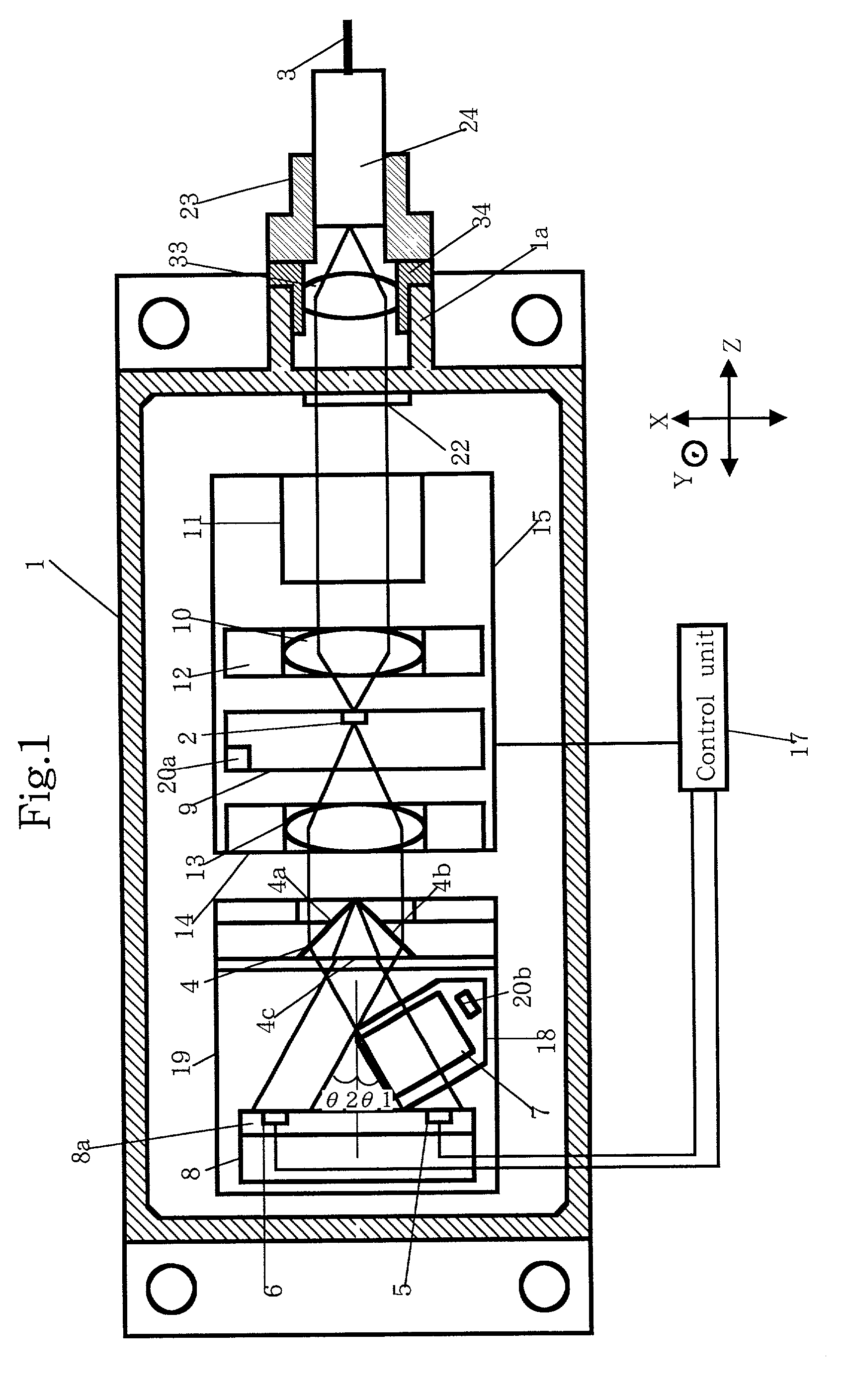
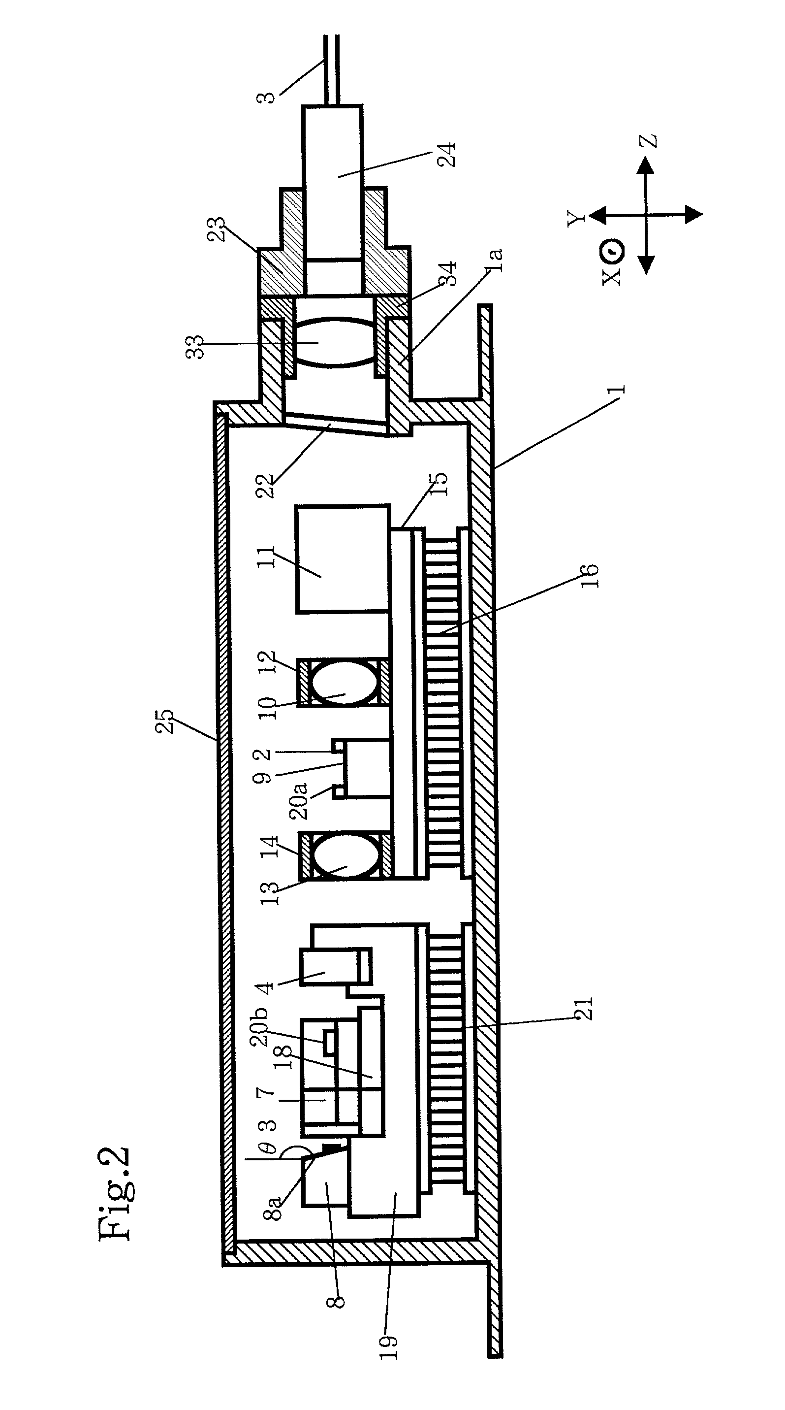
[0077] A process of making the optical module according to the present invention will be described below.
[0078] First of all, the LD carrier on which the semiconductor laser element 2 is mounted, the optical isolator 11, the first lens holder 12 and the second lens holder 14 are fixedly mounted on the first base 15 through soldering.
[0079] Thereafter, the first base 15 is soldered onto the first cooling device 16 that has already been mounted in the package 1. Similarly, the second base 19 having no matter mounted on the top thereof is fixedly mounted on the second cooling device 21 that has already been mounted in the package 1.
[0080] Next, the prism 4 is properly positioned relative to the X-axis direction such that the monitoring laser beam outputted from the back end face of the semiconductor laser element 2 will enter the two sloped faces 4a and 4c of the prism 4. Subsequently, the prism 4 is brought into abutment with the first protrusion 19a of the second base 19 and fixedly ...
third embodiment
[0094] FIG. 6A is a plan view of an optical filter used in an optical module according to the present invention while FIG. 6B illustrates the rotation of the optical filter. FIG. 7 is a side view of the optical filter shown in FIG. 6: FIG. 7A shows the optical filter rotatably supported on a base and FIG. 7B shows the optical filter fixedly mounted on the base.
[0095] Referring to FIGS. 6A and B, the optical filter 7 used in an optical module according to the third embodiment of the present invention is characterized by that it is fixedly mounted on a disc-shaped filter holder 28 that is rotatable about a rotation axis L perpendicular to the direction of incident laser beam. This rotation axis L is one that passes through the intersection between the diagonal lines in the square optical filter 7, as shown in FIG. 6B.
[0096] As shown in FIG. 7A, the optical filter 7 is fixedly mounted, at its bottom, on a filter holder 28 through low temperature glass or adhesive. The bottom of the opt...
fourth embodiment
[0098] FIGS. 8A and B are side and plan cross-sectional views of a holder member used in an optical filter according to the present invention; FIG. 9A is a plane view showing the holder member of FIG. 8 before it is fixedly mounted on the base while FIG. 9B is a plan view showing the same holder member after it has fixedly been mounted on the base; FIGS. 10A and B are side cross-sectional and plan views showing the state of the holder member of FIG. 8 when the optical filter is been angularly adjusted by an angle adjusting tool.
[0099] Referring to FIG. 8, the optical module according to the fourth embodiment of the present invention includes a prism 4, optical filter 7 and PD carrier 8, all of which are fixedly mounted in a holder member 29 consisting of a hollow metal block.
[0100] The optical filter 7 is mounted on a filter holder 30 that is fixedly mounted on the holder member 29 in such a manner as shown in connection with the third embodiment. The filter holder 30 is a part inde...
PUM
 Abstract
Description
Claims
Application Information
 - R&D
- Intellectual Property
- Life Sciences
- Materials
- Tech Scout
- Unparalleled Data Quality
- Higher Quality Content
- 60% Fewer Hallucinations
Browse by: Latest US Patents, China's latest patents, Technical Efficacy Thesaurus, Application Domain, Technology Topic, Popular Technical Reports.
© 2025 PatSnap. All rights reserved.Legal|Privacy policy|Modern Slavery Act Transparency Statement|Sitemap|About US| Contact US: help@patsnap.com


