
In-ground pest bait station

Inactive Publication Date: 2002-09-12
CLARK PEST CONTROL OF STOCKTON
View PDF0 Cites 21 Cited by
  • Summary
  • Abstract
  • Description
  • Claims
  • Application Information

AI Technical Summary

Benefits of technology

[0007] Accordingly, it is an advantage of the present invention that it is placed in the ground, and is therefore relatively inaccessible to children and pets.
[0008] It is a further advantage of the present invention that it controls evaporation of liquid bait by placing such bait substantially in the ground, moderating the temperature and therefore the evaporation rate of the liquid bait.
[0009] It is a further advantage of the present invention that it controls evaporation of liquid bait by placing such bait in a substantially enclosed environment, with a removable cap for easy access to inner portions of the bait station.
[0010] It is a further advantage of the present invention that its entry ports can be adjusted in size so as to accommodate pests of different sizes.
[0011] It is a further advantage of the present invention that it can simultaneously accommodate liquid bait, solid bait, and an area for insertion of a sticky monitor card for the capture of pests. A sticky monitor card is a card with an adhesive surface designed to capture insects and other pests by trapping them on its adhesive surface.
[0012] The present invention provides an in-ground device and system for controlling pests. It is generally comprised of a housing, a reservoir, a bait tray, a cap and, optionally, a reservoir access.

Problems solved by technology

Some of these devices trap pests within the device, either by mechanical barriers or by sticky surfaces.
First, because some baits may be dangerous to people and pets, it is important that the bait be relatively inaccessible to children and pets, but fully accessible to the targeted pests.
Second, although liquid bait can be more effective, it is also subject to evaporation, thereby necessitating inconvenient monitoring and refilling of the liquid.

Method used


Image

  • In-ground pest bait station
  • In-ground pest bait station
  • In-ground pest bait station

Examples


Embodiment Construction

.

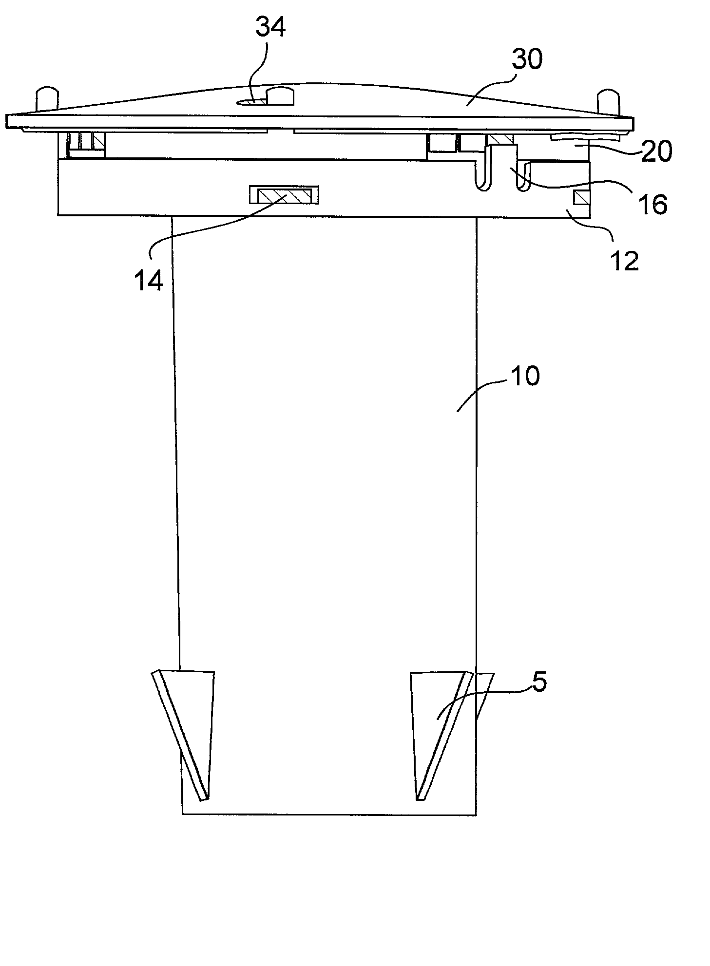
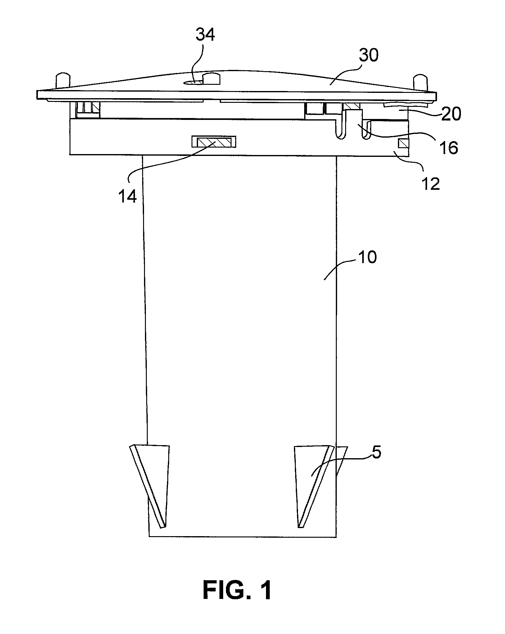
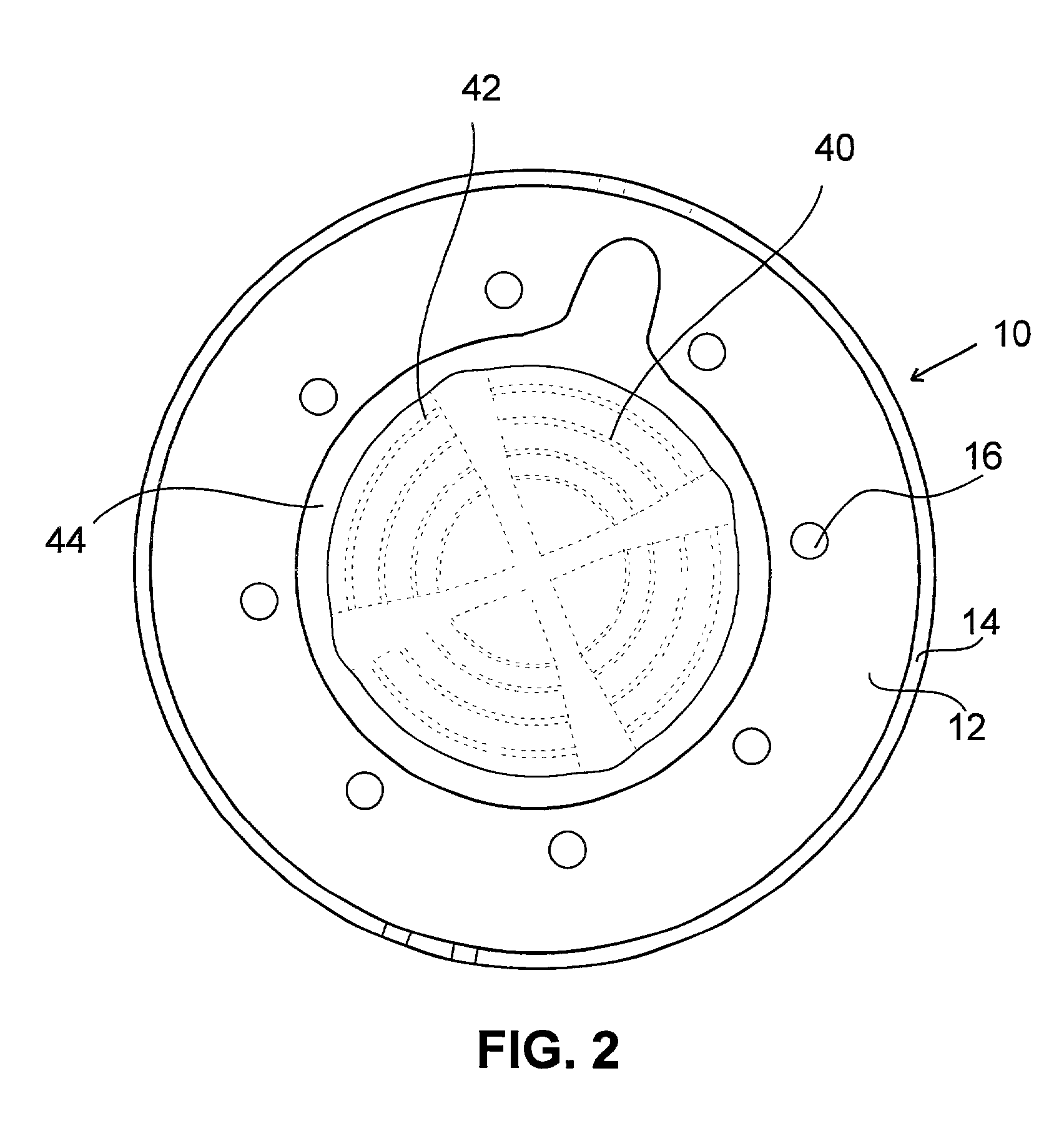
[0033] A preferred embodiment of a bait station in accordance with the present invention will now be discussed with reference to FIGS. 1-10.

[0034] Referring first to FIGS. 1 and 6, a housing is designated by the reference numeral 10, a bait tray is designated by the reference numeral 20, and a cap is designated by the numeral 30. In this embodiment, housing 10 has a circular cross section.

[0035] Referring to the bait station illustrated by FIGS. 1-6, housing 10 is fixedly implanted in the ground. A plurality of outwardly extending elements 5, including, but not limited to, generally wedge shaped fins or protuberances, semi-circular shaped protuberances, rectangular shaped protuberances or square shaped protuberances, are mounted to the outer surface of housing 10. Preferably the elements 5 extend outwardly in a radial orientation and are arranged along the outer surface of housing 10. Elements 5 are provided to prevent dislodgment and rotation of housing 10 once it is implanted int...


PUM


Abstract

An in-ground bait station for pest detection and control includes a first housing tube fixedly implanted into the ground and a removable reservoir within the housing. The reservoir contains pesticide for detecting and controlling pest activity, and can be inspected or replaced by removing the reservoir from the housing. The bait station further includes a cap to provide evaporation control and tampering resistance when the reservoir and housing are installed below ground and to provide an additional receptacle containing bait for detecting and controlling pest activity. The cap includes a detachable bait tray. The bait tray contains a receptacle between an inner and outer edge for holding bait. The bait tray is designed to cooperate with the housing to oppose rotational movement of the cap when the bait station is in an operational state. The cap is designed to cooperate with the bait tray to provide evaporation control and tampering resistance when the housing and bait tray are installed in the ground.

Description

1. FIELD OF THE INVENTION[0001] The present invention relates generally to bait stations, and more particularly to in-ground pest bait stations containing liquid and non-liquid bait and sticky monitor cards.2. BACKGROUND OF THE INVENTION[0002] Various devices have been developed to help control insect pest populations. Some of these devices trap pests within the device, either by mechanical barriers or by sticky surfaces. Other devices contain poison bait, in either liquid or non-liquid form.[0003] For example, U.S. Pat. No. 5,966,863 to Payton et al. discloses a multi-compartment liquid bait station for control of ants. Another liquid bait station is disclosed in U.S. Pat. No. 5,943,816 to Hyatt et al., which describes a liquid bait station with capillary feeding pores. Similarly, U.S. Pat. No. 5,875,586 to Ballard et al., refers to dispensing liquid bait in a refillable manner, including a transparent bait station into which liquid bait may be injected. U.S. Pat. No. 5,802,761 to ...

Claims


Application Information

Patent Timeline
IPC IPC(8): A01M1/02A01M1/20A01M31/00
CPCA01M1/026A01M1/2011A01M31/002A01M2200/011
Inventor CLARK, TERRY J.
Owner CLARK PEST CONTROL OF STOCKTON
Learn More