
Printing apparatus

a technology of printing apparatus and printing plate, which is applied in the direction of printing mechanism, visual presentation using printer, instruments, etc., can solve the problems of dimensional error, accuracy of driving and braking control for scanning, and accuracy of distance indicated by d

Inactive Publication Date: 2002-08-22
SEIKO EPSON CORP
View PDF0 Cites 46 Cited by
  • Summary
  • Abstract
  • Description
  • Claims
  • Application Information

AI Technical Summary

Problems solved by technology

The former has limits in accuracy of driving and braking control for scanning, and resulting accuracy of positioning control.
However, in arranging the print heads PH(1) and PH(2) as shown in FIG. 12, the accuracy of the distance indicated by d in the figure causes a problem.
Further, even if the arrangement may be possible, for the time being, a dimensional error occurs due to changes in temperatures of the print heads themselves.
As a result, due to lowered accuracy of the inter-nozzle arrangement, a dot line L1A printed by the nozzle J1A and a dot line J21 printed by the nozzle J21 can appear to have a blank line between them differently from boundaries between other dot lines, causing a noticeably degraded print image quality.
In short, due to a low inter-nozzle position accuracy, the print quality is degraded.

Method used


Image

  • Printing apparatus
  • Printing apparatus
  • Printing apparatus

Examples


Embodiment Construction

[0058] The invention will now be described in detail with reference to the drawings showing an embodiment thereof. In the embodiment, a printing apparatus according to the invention is applied to an image printing system.

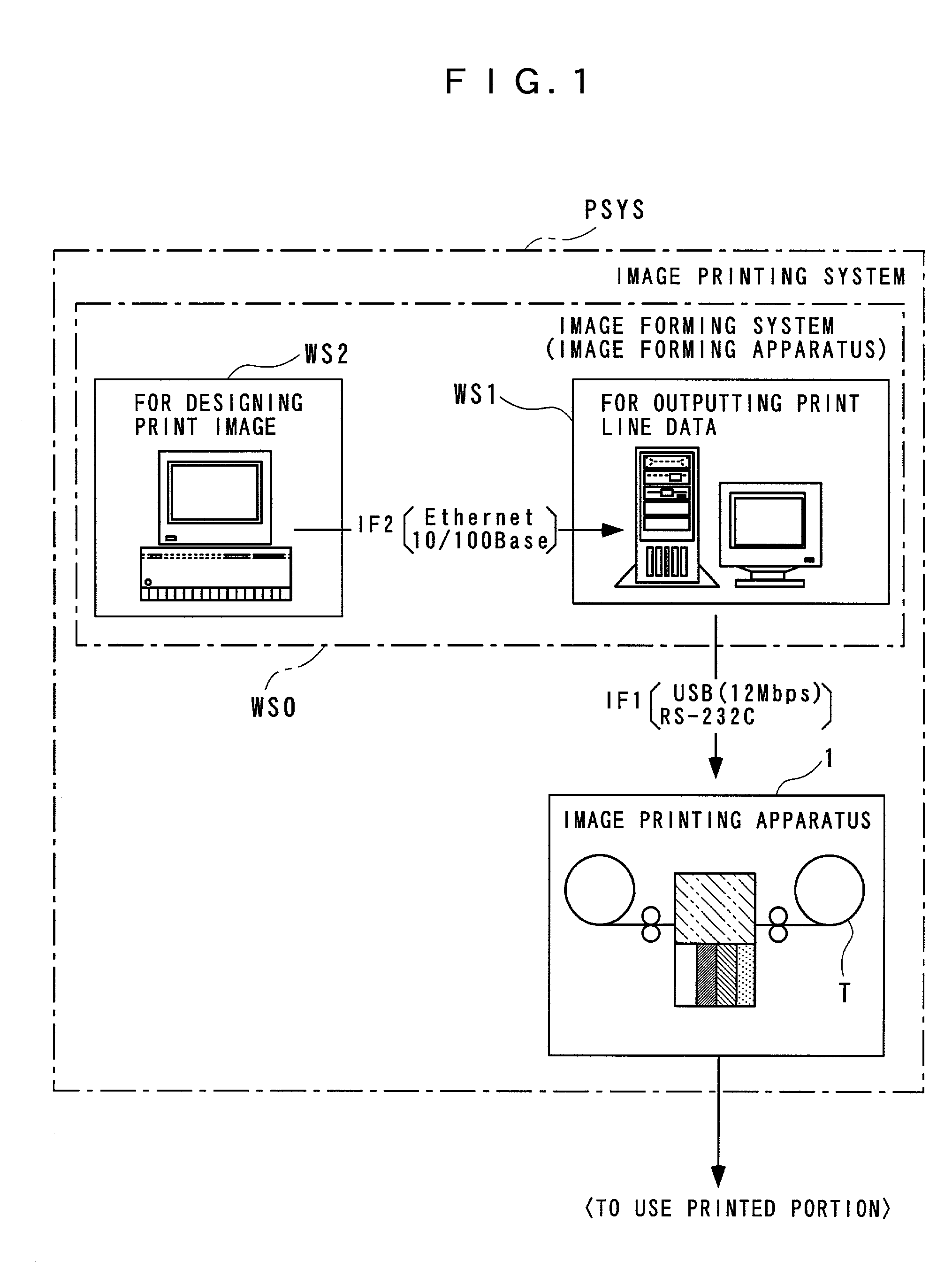
[0059] Referring first to FIG. 1, the image printing system PSYS includes am image forming system (or apparatus) WS0 including a personal computer, an engineering work station (EWS) or the like for forming print image data representing a desired print image, and the image printing apparatus 1 for printing a print image based on the print image data. The print image data formed by the image forming system WS0 is transferred (sent) to the image printing apparatus 1 via a first interface IF1 in units of line data items each representing one line of the print image data.

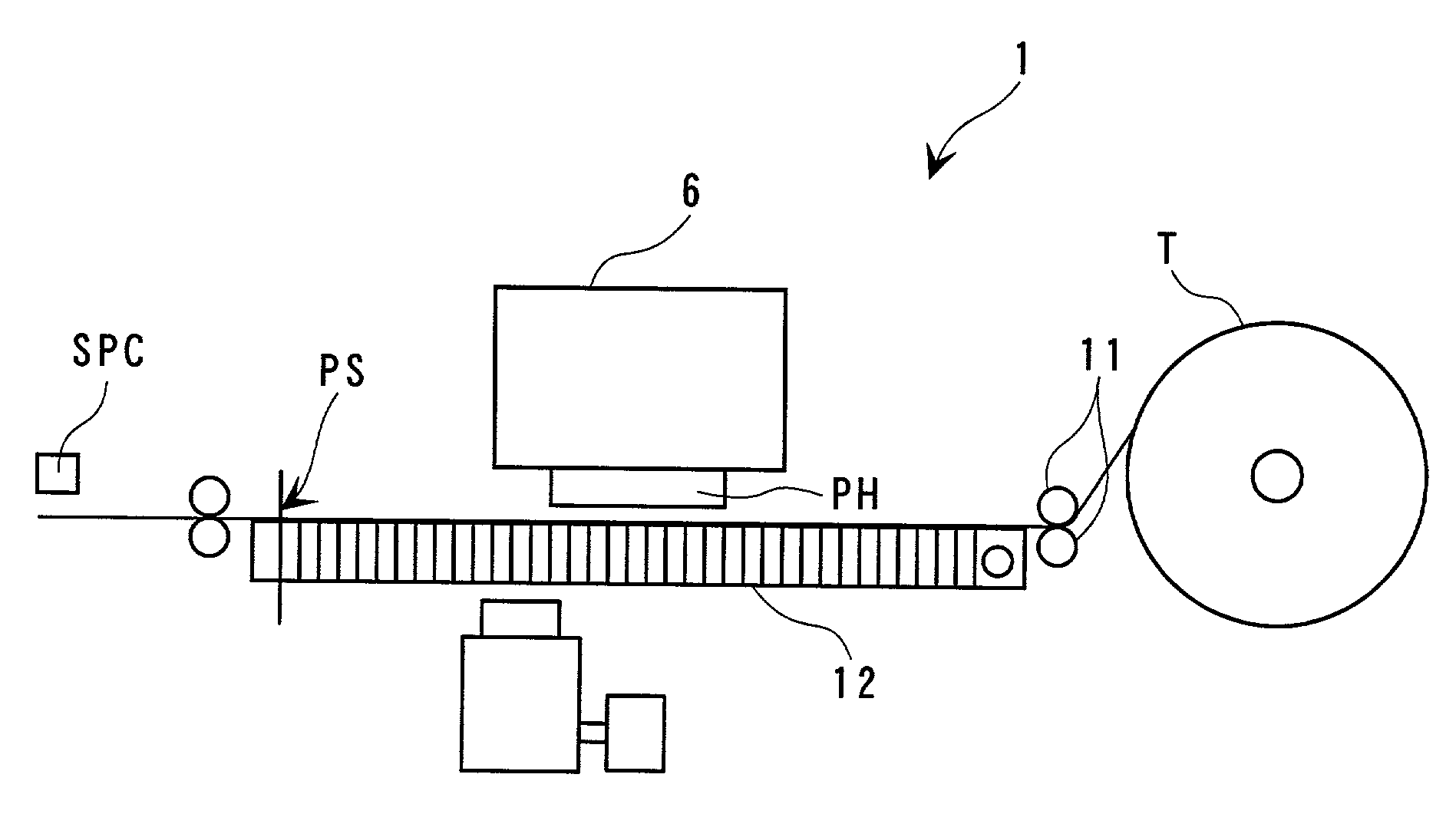
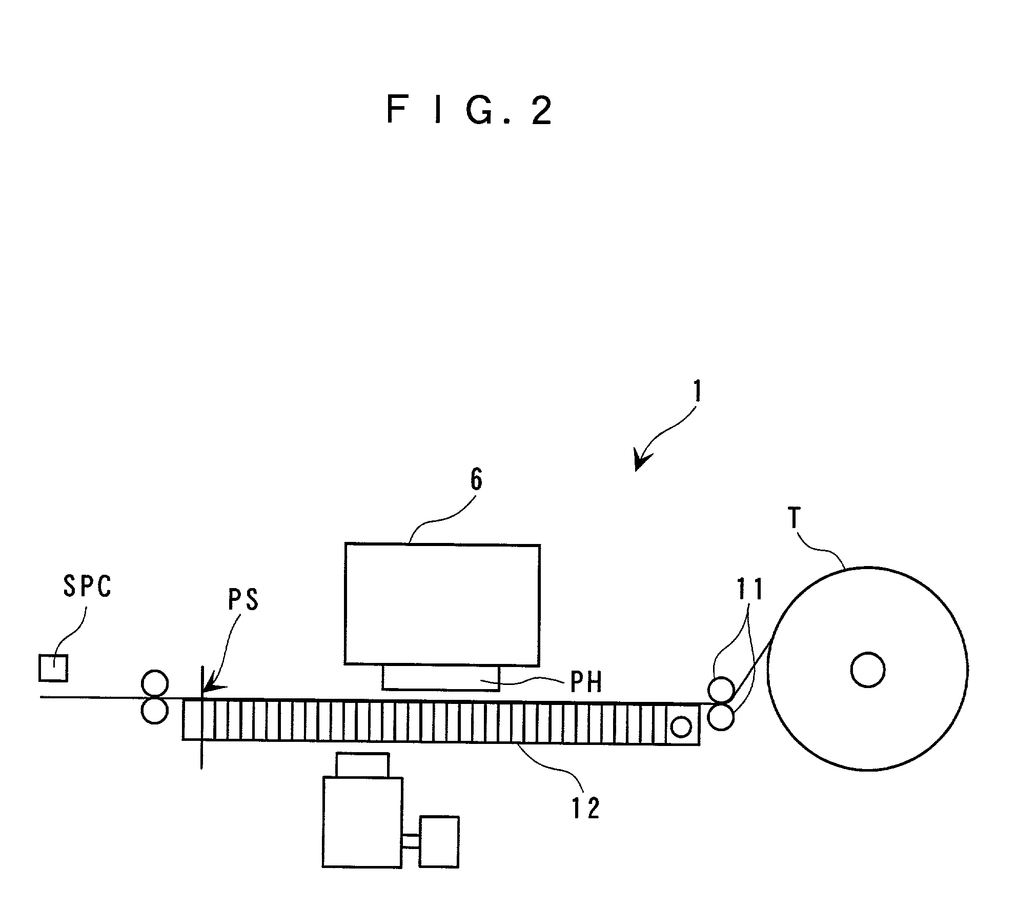
[0060] Next, as shown in FIGS. 1 to 3, in the image printing apparatus 1, a tape T supplied (mounted) in a state wound around a tape reel (on a right-hand side as viewed in the figures) is used as a prin...


PUM


Abstract

There is provided a printing apparatus which is capable of increasing the printing speed by employing a multi-head structure while maintaining or enhancing print quality. The printing apparatus prints on a print medium by using N print heads, where N is an integer equal to or larger than 2, assuming that two axes orthogonal to each other on a two-dimensional rectangular coordinate system are set to an X axis and a Y axis, each of the print heads being capable of printing M dots in a direction along the Y axis simultaneously, where M is an integer equal to or larger than 3, and at the same capable of printing M dot lines each extending in a direction along the X axis, by relative scan on the print medium in the direction along the X axis, the M dot lines being arranged side by side in the direction along the Y axis. At least two print heads of the N print heads are arranged in a manner such that selected ones of the M dot lines that can be printed by one of the at least two print heads overlap selected ones of the M dot lines that can be printed by another of the at least two print heads.

Description

[0001] 1. Field of the Invention[0002] This invention relates to a printing apparatus.[0003] 2. Prior Art[0004] There has been a demand for a printing apparatus capable of printing a large-sized or a large-volume image (including an image having a large number of dots due to high density of the image) at a higher speed. In the case of a printing apparatus whose print head is caused to scan a print medium for printing, a possible solution to an increased printing speed is to increase the scanning speed or increase a printable quantity per scan. The former has limits in accuracy of driving and braking control for scanning, and resulting accuracy of positioning control. On the other hand, the latter is capable of increasing the printable quantity per scan, in theory, by using a plurality of print heads (so-called multi-head).[0005] For instance, as shown in FIG. 13, by using N print heads, PH(1), PH(2) where N is an integer equal to or lager than 2 (in the illustrated example, N=2), a ...

Claims


Application Information

Patent Timeline
Patent Type & Authority Applications(United States)
IPC IPC(8): B41J2/21B41J2/01B41J2/345B41J2/51B41J11/00G06K15/10
CPCB41J2/2103B41J2/51B41J11/001G06K15/105G06K2215/0094
Inventor MOROZUMI, KAZUAKISUYAMA, KIYOSHIOTSUKA, NOBUTOSHIYAMAZAKI, ATSUSHI
Owner SEIKO EPSON CORP
Learn More