
Fuel injection control system and method and engine control unit for internal combustion engine

Inactive Publication Date: 2002-05-23
HONDA MOTOR CO LTD
View PDF0 Cites 6 Cited by
  • Summary
  • Abstract
  • Description
  • Claims
  • Application Information

AI Technical Summary

Benefits of technology

[0024] This fuel injection control method provides the same advantageous effects as described above concerning the fuel injection control system according to the first aspect of the invention.
[0025] To attain the above object, according to a third aspect of the invention, there is provided an engine control unit including a control program for causing a computer to carry out fuel injection control of an internal combustion engine including intake cams and exhaust cams for opening and closing respective intake valves and exhaust valves, wherein a cam phase as a phase of at least one of each intake cam and each exhaust cam relative to a crankshaft is changeable, and at least one of the intake cam and the exhaust cam can be switched to one of a plurality of kinds of cams having respective profiles different from each other.
[0026] The engine control unit according to the third aspect of the invention is characterized in that the control program causes the computer to detect a rotational speed of said engine, detect the cam phase, determine an intake pipe pressure parameter representative of an intake pipe pressure, determine a first parameter in dependence on the one of the plurality of cams to which the at least one of the intake cam and the exhaust cam is switched, the detected rotational speed of the engine, and the detected cam phase, determine a second parameter in dependence on the one of the plurality of cams to which the at least one of the intake cam and the exhaust cam is switched, the detected rotational speed of the engine, and the detected cam phase, and calculate an amount of fuel to be injected, by using a linear equation of the intake pipe pressure parameter, the linear equation having a slope of the first parameter and an intercept of the second parameter.
[0027] This engine control unit provides the same advantageous effects as described above concerning the fuel injection control system according to the first aspect of the invention.
[0028] Preferably, the first parameter is set to a larger value as the detected rotational speed of the engine is higher and the detected cam phase is more retarded.
[0029] Preferably, the second parameter is set to a larger value as the detected rotational speed of the engine is higher and the detected cam phase is more retarded.

Problems solved by technology

However, in both of the former and latter fuel injection control systems, the fuel injection amount is calculated based on the charging efficiency based on only one of the two types of variable valve mechanisms, and hence the control system incorporating them cannot calculate the fuel injection amount as a value suited to the charging efficiency at the time, so that the fuel injection control cannot be performed properly, causing e.g. degraded drivability and increased exhaust emissions.
Further, a combination of the above two fuel injection control systems would require a large number of maps of preset values to determine the fuel injection amount, and the calculating process becomes complicated.

Method used


Image

  • Fuel injection control system and method and engine control unit for internal combustion engine
  • Fuel injection control system and method and engine control unit for internal combustion engine
  • Fuel injection control system and method and engine control unit for internal combustion engine

Examples


Embodiment Construction

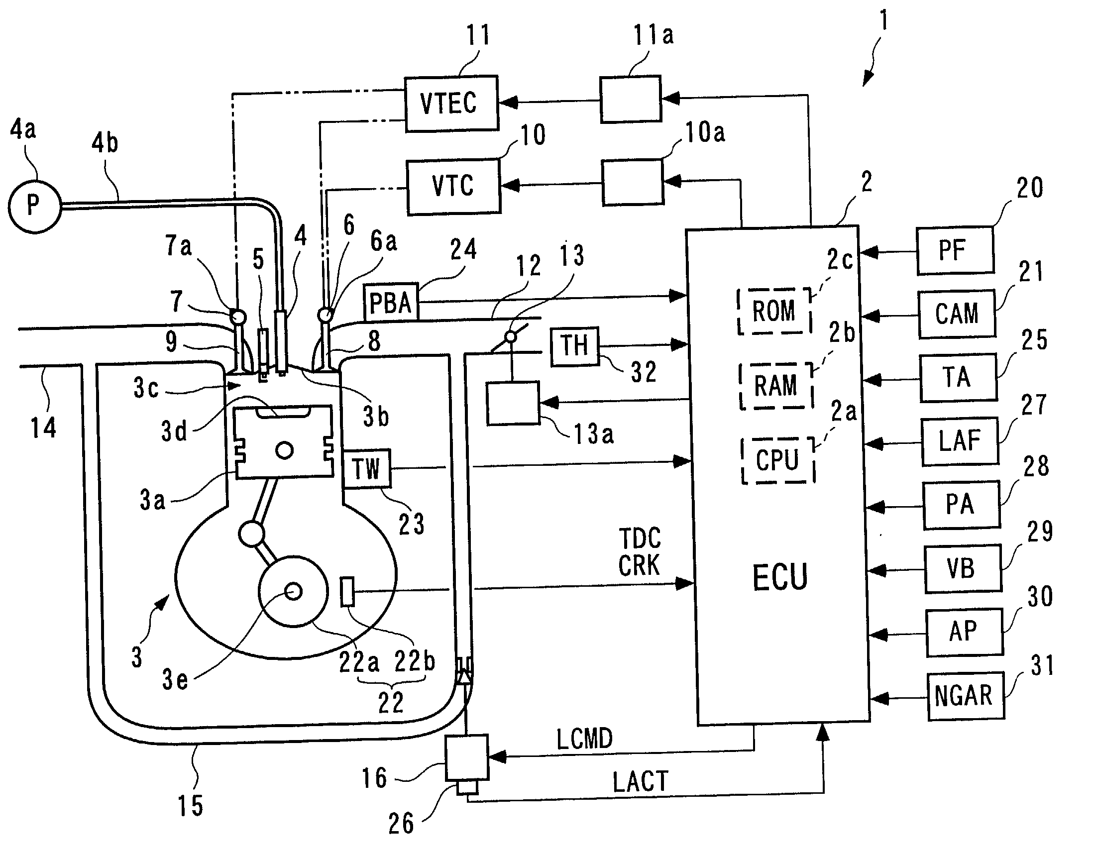
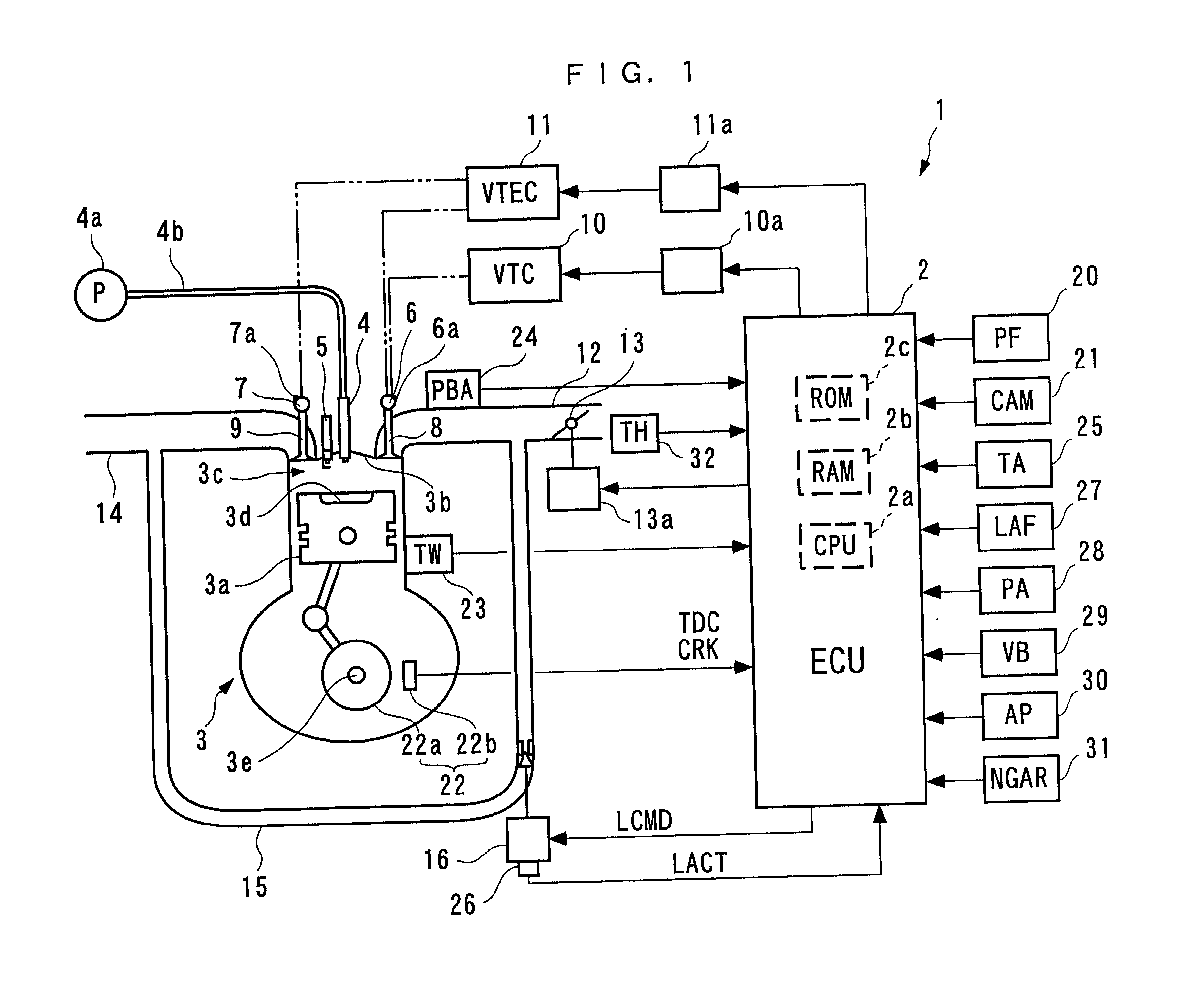
[0063] The invention will now be described in detail with reference to the drawings showing a preferred embodiment thereof. Referring first to FIG. 1, there is schematically shown the arrangement of a fuel injection control system for an internal combustion engine, according to an embodiment of the invention. As shown in the figure, the fuel injection control system 1 includes an ECU 2. The ECU 2 carries out a fuel injection control process, an ignition timing control process, and a combustion mode transition-determining process for the internal combustion engine 3 (hereinafter simply referred to as "the engine 3").

[0064] The engine 3 is a straight type four-cylinder gasoline engine for an automotive vehicle, not shown. The engine 3 has four cylinders (only one of which is shown) in each of which a combustion chamber 3c is formed between the piston 3a and a cylinder head 3b. The piston 3a has a central portion of a top surface thereof formed with a recess 3d. The cylinder head 3b ha...


PUM


Abstract

There are provided a control system and method and an engine control unit for an internal combustion engine including two types of variable valve mechanisms capable of changing a camp phase and a cam profile, respectively, which system is capable of determining an amount of fuel to be injected as a value suited to charging efficiency at the time by simplified calculation processing, thereby performing the fuel injection control properly in a simplified manner. The fuel injection control system includes an ECU. The ECU searches a map for a multiplier term Ati for a high-speed cam or low-speed cam based on the rotational speed of the engine and the cam phase, and a map for an addend term Bti for the high-speed cam or the low-speed cam based on the rotational speed of the engine and the cam phase. The ECU calculates a basic fuel injection time period Tibase as the sum of the product of an intake pipe absolute pressure PBA and the multiplier term Ati and the addend term Bti (Ati.times.PBA+Bti).

Description

BACKGROUND OF THE INVENTION[0001] 1. Field of the Invention[0002] This invention relates to a fuel injection control system and method and an engine control unit for an internal combustion engine having two types of variable valve mechanisms each of which changes the cam phase and the cam profile of at least one of each intake cam and each exhaust cam for opening and closing respective intake and exhaust valves.[0003] 2. Description of the Prior Art[0004] Conventionally, a fuel injection control system for an internal combustion engine has been proposed in Japanese Laid-Open Patent Publication (Kokai) No. 11-301144, which includes a variable valve mechanism. The variable valve mechanism of the proposed fuel injection control system changes the phase angle of intake cam (hereinafter referred to as "the cam phase") of each intake cam with respect to a crankshaft, whereby the valve timing of the intake valve, i.e. the valve overlap of the intake valve and an associated exhaust valve is...

Claims


Application Information

Patent Timeline
IPC IPC(8): F02D43/00F01L1/26F01L1/34F01L13/00F02B17/00F02B23/10F02B75/12F02D13/02F02D41/00F02D41/02F02D41/30F02D41/34F02D41/40F02F3/26
CPCF01L1/267Y02T10/42F01L13/0036F01L2001/0537F01L2710/00F01L2800/00F02B17/005F02B23/10F02B23/101F02B2023/102F02B2075/125F02B2275/18F02D13/0219F02D13/0261F02D41/0002F02D41/3029F02D41/3064F02D41/34F02D41/402F02D2041/001F02D2200/0406F02F3/26Y02T10/125Y02T10/18Y02T10/44Y02T10/123F01L1/34F02D41/40F02D2041/0265Y02T10/12Y02T10/40
Inventor OGAWA, KENKOHDA, YUTAKATAGAMI, HIROSHIUEDA, KAZUHIRO
Owner HONDA MOTOR CO LTD
Learn More