User identity authentication system and user identity authenication method and mobile telephonic device
a mobile telephonic device and user identity technology, applied in the field of user identity authentication system and user identity authentication method, can solve the problems of increased communication cost, password abuse, and difficult authentication of user identity
- Summary
- Abstract
- Description
- Claims
- Application Information
AI Technical Summary
Problems solved by technology
Method used
Image
Examples
embodiment 1
[0062] Configurations and operations of the mobile information communication device including the sensor built-in type display according to the present invention will be explained with Embodiments 1 to 8.
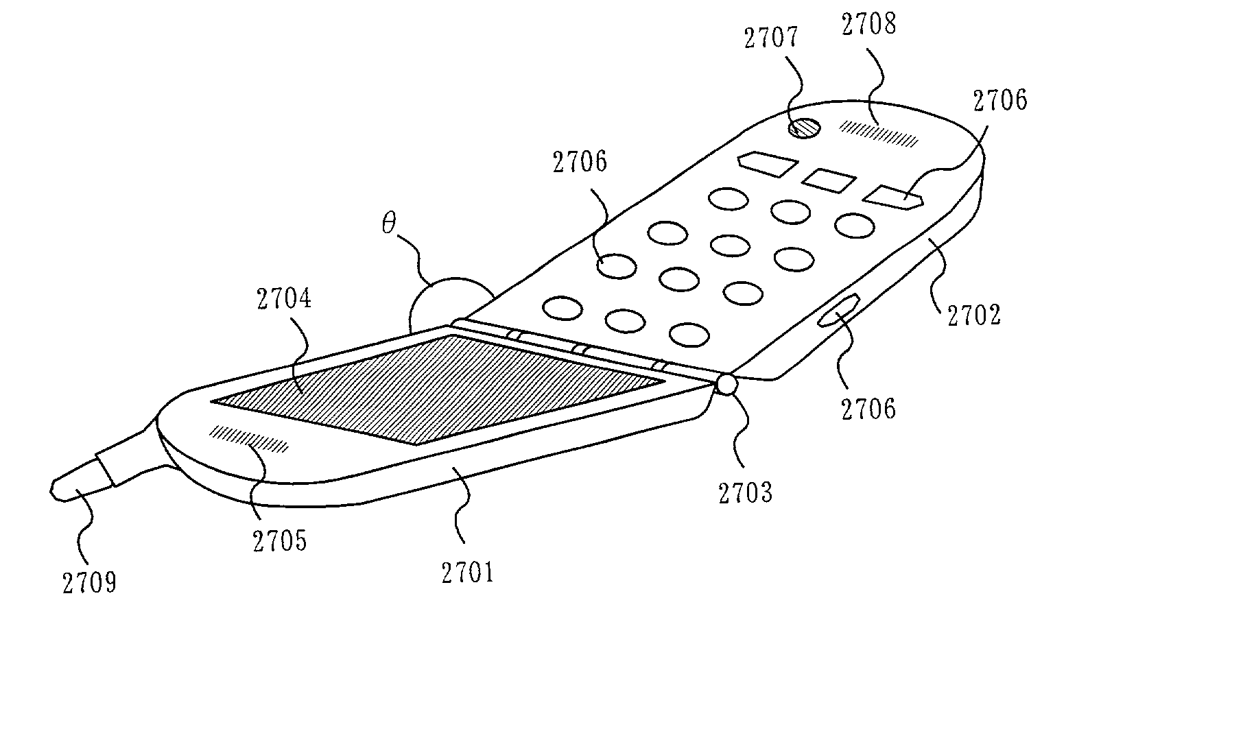
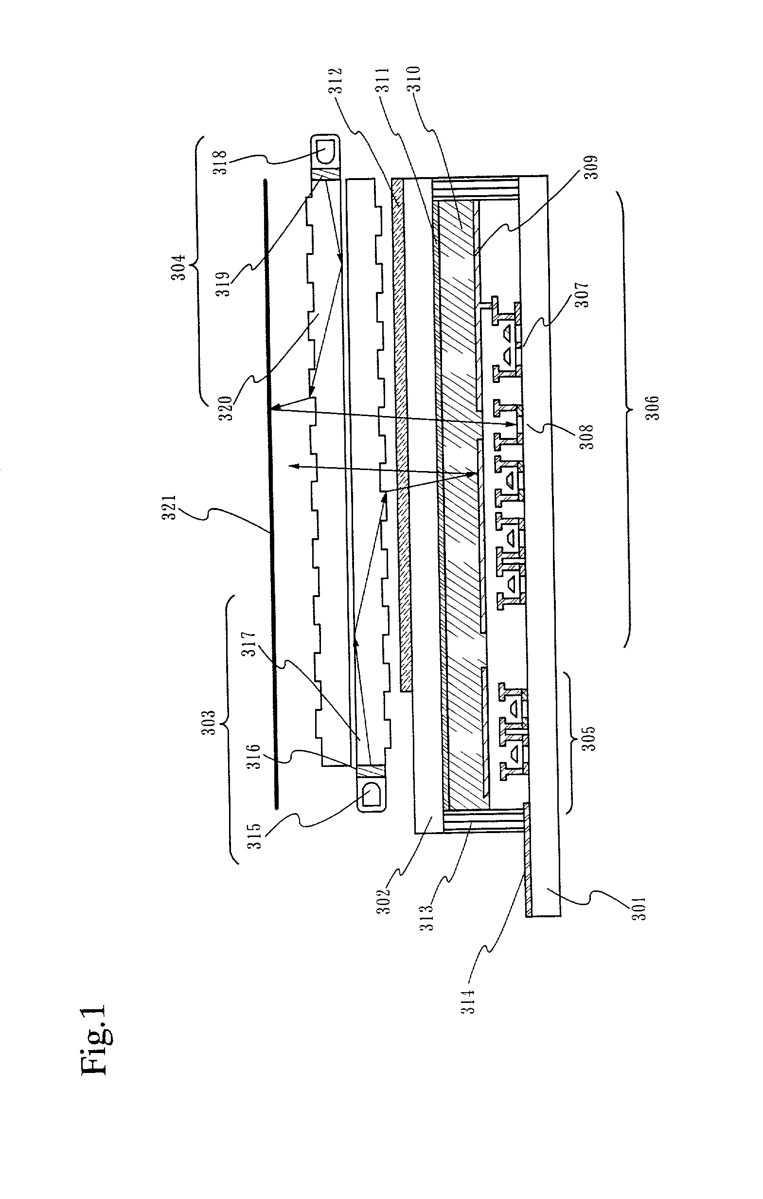
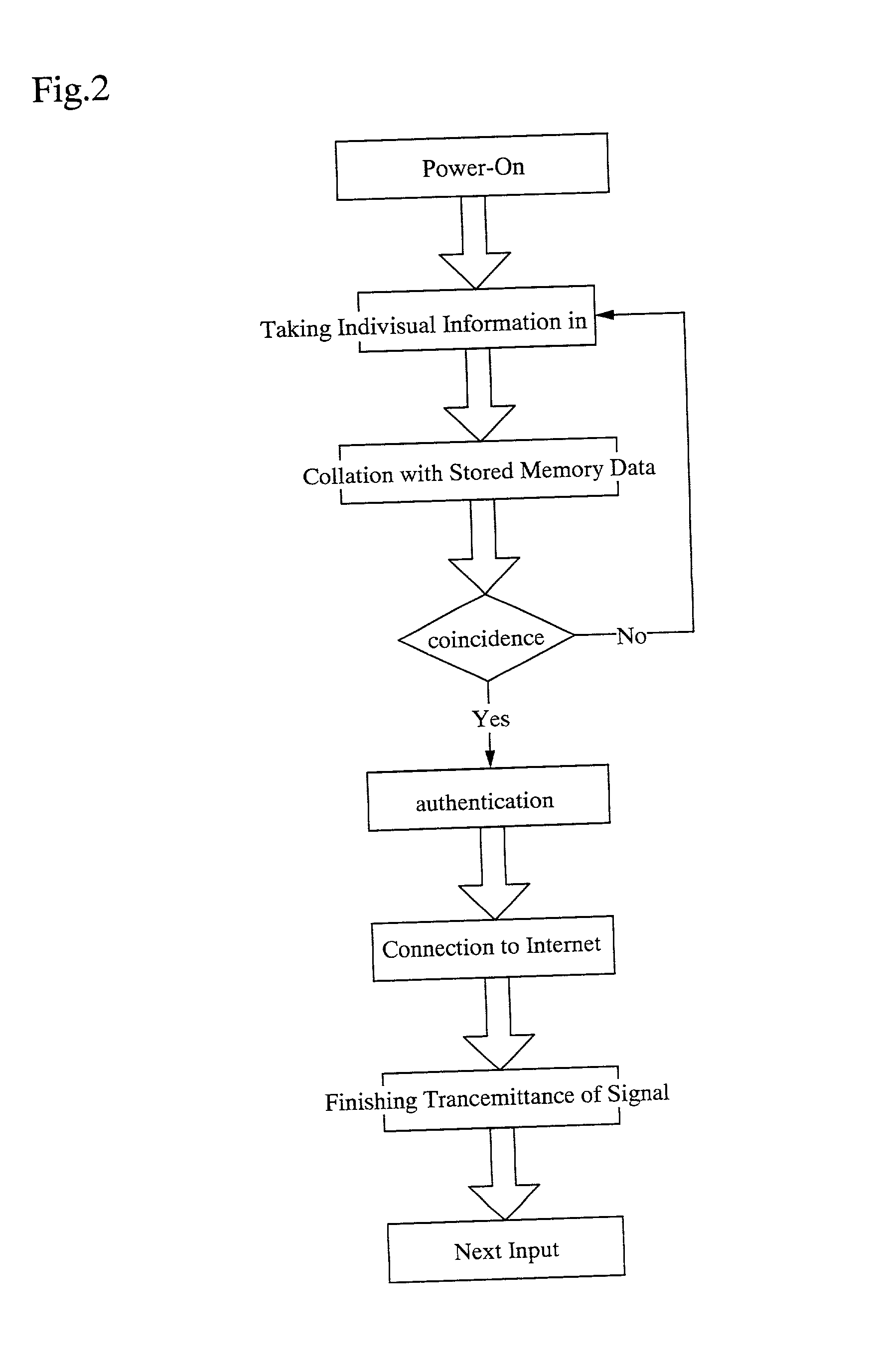
[0063] FIG. 6 is a block diagram showing the mobile information communication device in the embodiment 1. This mobile information communication device includes an antenna 601, a transmitting / receiving circuit 602, a signal processing circuit 603 for compressing / expanding and coding the signals, a control microcomputer 604, a flash memory 605, a keyboard 606, a voice input circuit 607, a voice output circuit 608, a microphone 609 and a loudspeaker 610, which are the same configuration as the conventional device. In addition to the above, the present mobile information communication device includes an image sensor built-in display 611 and a collating circuit 612.
[0064] When collation is performed, analog image data obtained by the sensor incorporated into the display are converted int...
embodiment 2
[0067] FIG. 7 is a block diagram showing a structure of the sensor built-in type display used in the present invention. This display includes a source signal line driver circuit 120, a gate signal line driver circuit 122. The display further includes a sensor source signal line driver circuit 121 and a sensor gate signal line driver circuit 123, which control driving of a reset TFT, a buffer TFT and a selection TFT, which are provided for each pixel. Note that the source signal line driver circuit 120, the gate signal line driver circuit 122, the sensor source signal line driver circuit 121, the sensor gate signal line driver circuit 123 are generically called a driver circuit portion in this specification.
[0068] The source signal line driver circuit 120 has a shift register 120a, a latch (A) 120b and a latch (B) 120c. A clock signal (CLK) and a start pulse (SP) are inputted to the shift register 120a of the source signal line driver circuit 120. The shift register 120a sequentially...
embodiment 3
[0085] FIG. 10 is a diagram showing circuits of a sensor portion with a different configuration from the sensor portion in the embodiment 2. A pixel / sensor portion 1001 is provided with the source signal lines S1 to Sx, the gate signal lines G1 to Gy, the capacitance lines CS1 to CSy, the reset gate signal lines RG1 to RGy, the sensor output wirings SS1 to SSx and the sensor power source line VB.
[0086] The pixel / sensor portion 1001 has a plurality of pixels 1002. The pixel 1002 includes any one of the source signal lines S1 to Sx, any one of the gate signal lines G1 to Gy, any one of the capacitance lines CS1 to CSy, any one of the reset gate signal lines RG1 to RGy, any one of the sensor output wirings SS1 to SSx, and the sensor power source line VB. The sensor output wirings SS1 to SSx are connected respectively to constant current power sources 1003-1 to 1003-x.
[0087] The pixel 1002 has a pixel TFT 1004, a storage capacitor 1007 and a liquid crystal element 1006. The pixel 1002 f...
PUM
 Abstract
Description
Claims
Application Information
 - R&D
- Intellectual Property
- Life Sciences
- Materials
- Tech Scout
- Unparalleled Data Quality
- Higher Quality Content
- 60% Fewer Hallucinations
Browse by: Latest US Patents, China's latest patents, Technical Efficacy Thesaurus, Application Domain, Technology Topic, Popular Technical Reports.
© 2025 PatSnap. All rights reserved.Legal|Privacy policy|Modern Slavery Act Transparency Statement|Sitemap|About US| Contact US: help@patsnap.com


