
Physiological tissue clipping apparatus, clipping method and clip unit mounting method

a tissue clipping and clipping device technology, applied in the field of tissue clipping apparatus, clipping method and clip unit mounting method, can solve the problems of difficult mounting work, difficult manipulation, and inability to ligate the target site, and achieve the effect of convenient handling

Inactive Publication Date: 2002-04-18
OLYMPUS CORP
View PDF2 Cites 212 Cited by
  • Summary
  • Abstract
  • Description
  • Claims
  • Application Information

AI Technical Summary

Benefits of technology

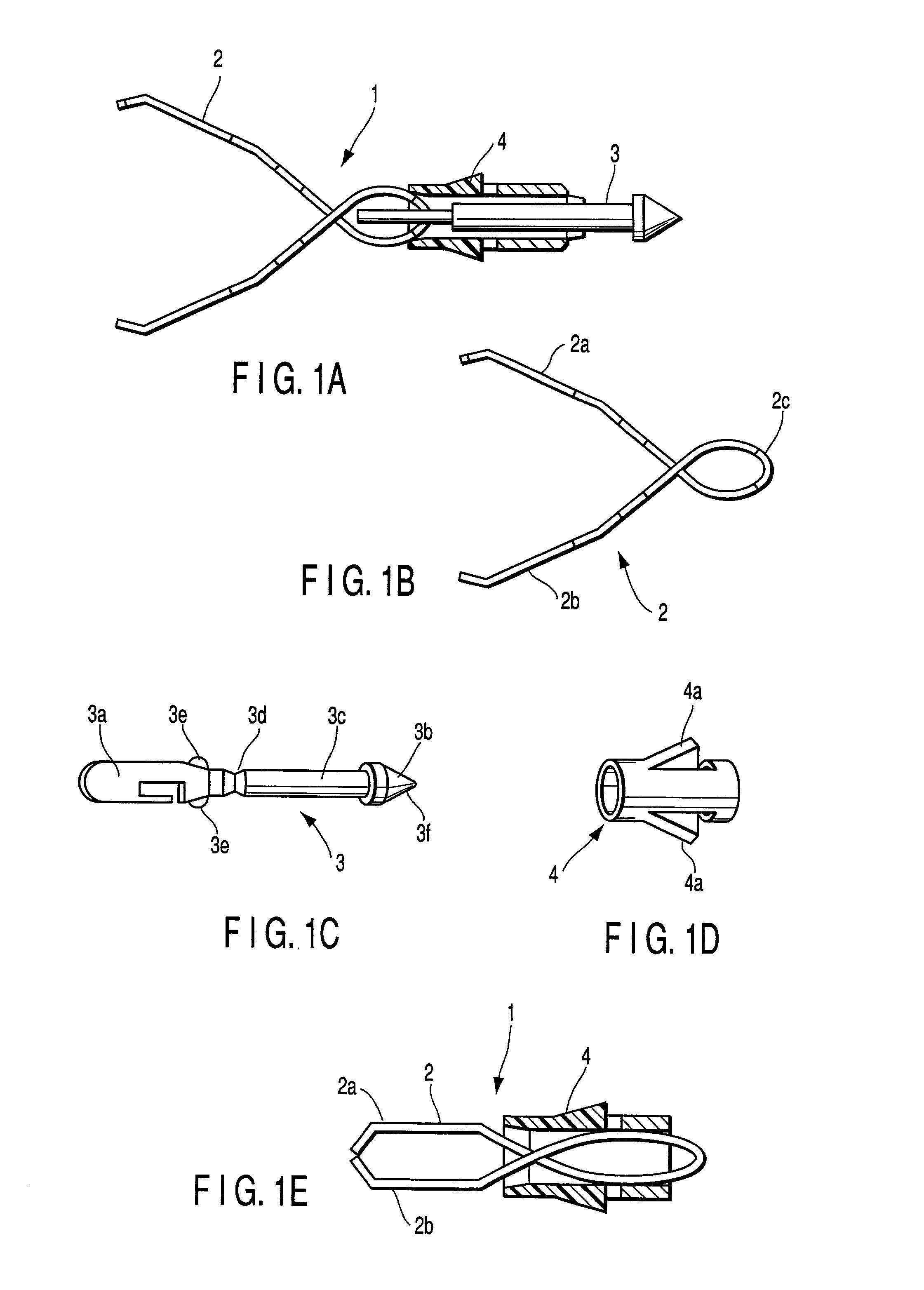
[0031] The present invention has been made in order to solve the foregoing problem. It is an object of the present invention to provide a physiological tissue clipping apparatus capable of inserting a clip into a physiological cavity while the clip is housed in an introducing tube, and further engaging the housed clip at the same time when the clip is released from the introducing tube merely by manipulating a manipulating member to be advanced and retracted, capable of ligating the clip, and capable of being easily handled.
[0069] According to the physiological tissue clipping method, a series of operations can be easily made such that the clip unit in the clip case is mounted on the clip manipulating device, this clip manipulating device is pulled toward the target site of the physiological tissue, and the clip unit is clipped at the physiological tissue.
[0077] According to the clip unit mounting method, a series of operations can be easily made such that the clip unit housed in the clip case is pulled in by the clip manipulating device, and the guided clip unit is mounted on the clip manipulating device.

Problems solved by technology

(1) the link member 103 of the clip unit 101 is held in a horizontal direction relevant to a cutout provided at the hook section 112;
(2) the pin 111 provided at the hook section 112 is engaged with the engagement hole 113b provided at the link section 113 while they are aligned with each other so that the pin 111 is engaged with the engagement hole 103b. Thus, two steps of (1) orientation and (2) alignment must be carried out at the same time, making it difficult to carry out a mounting work.
However, if manipulation is incorrect, the maximally opened state is passed, making it impossible to ligate the target site.
Thus, the slider section 116 must be carefully manipulated, which makes manipulation difficult.
However, when the introducing tube is bent, the manipulating wire slips out of an axial center of the introducing tube.
Therefore, when the clip unit is mounted on the hook section, the position of the hook section is changed according to the shape of the introducing tube, and can be safely fixed, thus making it difficult to mount the clip unit on the hook section.
Because of this, the length of the hook section is increased, the flexibility of the introducing tube is lost when the hook section is pulled into the introducing tube, making it difficult to ensure routing into a soft endoscope or protrusion of the hook section.
In order to facilitate fixing, when an elastic rubber ring with a small amount of force is employed, the release can be ensured with a small amount of force similarly, making it impossible to ensure reliably fixing.
Conversely, when an elastic rubber ring with a large amount of force is employed in order to make the release difficult, the fixing becomes heavy, makes it difficult to make manipulation.

Method used


Image

  • Physiological tissue clipping apparatus, clipping method and clip unit mounting method
  • Physiological tissue clipping apparatus, clipping method and clip unit mounting method
  • Physiological tissue clipping apparatus, clipping method and clip unit mounting method

Examples


second embodiment

[0161] FIG. 7A, FIG. 7B, and FIG. 8 each show a second embodiment according to the present invention. The present embodiment is identical to the first embodiment in configuration except the stop tube 4 of the clip unit 1 and the coil pipe 8 of the clip manipulating device 5 according to the first embodiment.

[0162] A coil pipe 13 according to the second embodiment is molded by processing a resilient metal pipe. The coil pipe 13 is formed in a substantially cylindrical shape as shown in FIG. 7A and FIG. 7B, where a small diameter section 13a whose inner diameter is small is provided at its tip end side, and a large diameter section 13b is provided at its proximal end. Further, an inclined section 13c is provided between the small diameter section 13a and the large diameter section 13b. Furthermore, at the coil pipe 13, as shown in FIG. 7A, four slits are provided at its tip end side, and an arm section 13d between the respective slits is elastically deformed so that the diameter of th...

third embodiment

[0168] FIG. 9A, FIG. 9B, FIG. 10A, and FIG. 10B each show a third embodiment according to the present invention. The present embodiment relates to a method of fixing the clip unit 1 to the clip manipulating device 5 according to the first embodiment. These embodiments are identical to each other except that the link member 3 of the clip unit 1 and the hook section 12 of the clip manipulating device 5 are shaped differently.

[0169] In the third embodiment, as shown in FIG. 9A, a link member 20 is formed by bending a metal wire. The proximal end side of the link member 20 is bent in a pentagonal shape having sides 20a, 20b, 20c, and 29d and an apex 20e. Further, as shown in FIG. 9B, a proximal end part 20f of the link member 20 is bent and molded by vertically shifting it. In addition, a hook section 21 is formed in a hollow pipe shape, as shown in FIG. 10A. As shown in FIG. 10B, there are provided: a large diameter section 21b having an inner diameter greater than a width W (refer to ...

fourth embodiment

[0172] FIG. 11A to FIG. 11C and FIG. 12 each show a fourth embodiment according to the present invention. The present embodiment relates to a method of fixing the clip unit 1 to the clip manipulating device 5 according to the first embodiment. These embodiments are identical to each other in configuration except that the link member 3 of the clip unit 1 and the hook section 12 of the clip manipulating device 5 are shaped differently.

[0173] In the fourth embodiment, as shown in FIG. 11A, a link member 22 is composed of a first link member 23 processed from a metal plate material and a second link member 24 obtained by bending and molding a metal plate material such as a plate spring material.

[0174] As shown in FIG. 1C, a claw shaped claw hook 23a is provided at a tip end side of the first link member 23 so as to be engaged with the clip 2. In addition, a T-shaped T hook 23b is provided to be fixed to the second link member at the proximal end side of the first link member 23. At the ...


PUM


Abstract

A clipping apparatus comprises a clip capable of being arbitrarily opened / closed, a stop tube for closing the clip, a link member capable of being inserted into the stop tube, and engaged with the clip, a sheath section capable of housing the clip and the stop tube therein, and a manipulating wire inserted into the sheath section. This clipping apparatus further comprises a hook section for, when the clip and the stop tube is protruded frontally of the sheath section, causing the sheath section and the stop tube to be engaged with each other, and disabling the stop tube from being housed in the sheath section again.

Description

BACKGROUND OF THE INVENTION[0001] 1. Field of the Invention[0002] The present invention relates to a physiological tissue clipping apparatus, clipping method and clip unit mounting method for inserting an endoscope into a cavity endoscopically, for example, and clipping a physiological tissue.[0003] 2. Description of the Related Art[0004] As a physiological tissue clipping apparatus, there is known a mechanism disclosed in Japanese Patent Application KOKAI Publication No. 8-19548, for example. This clipping apparatus is composed of a clip unit 10 and a clip manipulating device 106, as shown in FIG. 28A and FIG. 28B. The clip unit 101 causes a link member 103 to be engaged with a clip 102, and further, engages a clip tightening ring 104. A link member 103 is composed of a plate material, and an engagement hole 103b is provided to be linked with a hook section 112 of the clip manipulating device 106.[0005] The clip manipulating device 106 composed of an insert section 106a and a front...

Claims


Application Information

Patent Timeline
IPC IPC(8): A61B17/08A61B17/12A61B17/122A61B17/128
CPCA61B17/083A61B17/122A61B17/1222A61B17/1227A61B17/1285A61B2017/0053
Inventor KIMURA, KOHSUZUKI, TAKAYUKIWATANABE, HIROYOSHISHIRO, CHIKA
Owner OLYMPUS CORP
Learn More