
Apparatus, architecture and method for high-speed printing

a technology of apparatus and architecture, applied in the field of apparatus, architecture and high-speed printing, can solve the problems of limiting the overall speed of the system

Inactive Publication Date: 2002-03-21
SHUTTERFLY LLC
View PDF0 Cites 36 Cited by
  • Summary
  • Abstract
  • Description
  • Claims
  • Application Information

AI Technical Summary

Problems solved by technology

If the uncompression and the image processing are not fast enough, this function can become a bottleneck, limiting the overall speed of the system.
Any of these processes can become a bottleneck that limits the overall speed of the system.

Method used


Image

  • Apparatus, architecture and method for high-speed printing
  • Apparatus, architecture and method for high-speed printing
  • Apparatus, architecture and method for high-speed printing

Examples


Embodiment Construction

[0022] In the following detailed description of the preferred embodiments, reference is made to the accompanying drawings that form a part hereof, and in which are shown by way of illustration specific embodiments in which the invention may be practiced. It is understood that other embodiments may be utilized and structural changes may be made without departing from the scope of the present invention.

[0023] The leading digit(s) of reference numbers appearing in the Figures generally corresponds to the Figure number in which that component is first introduced, such that the same reference number is used throughout to refer to an identical component which appears in multiple Figures. The same reference number or label may refer to signals and connections, and the actual meaning will be clear from its use in the context of the description.

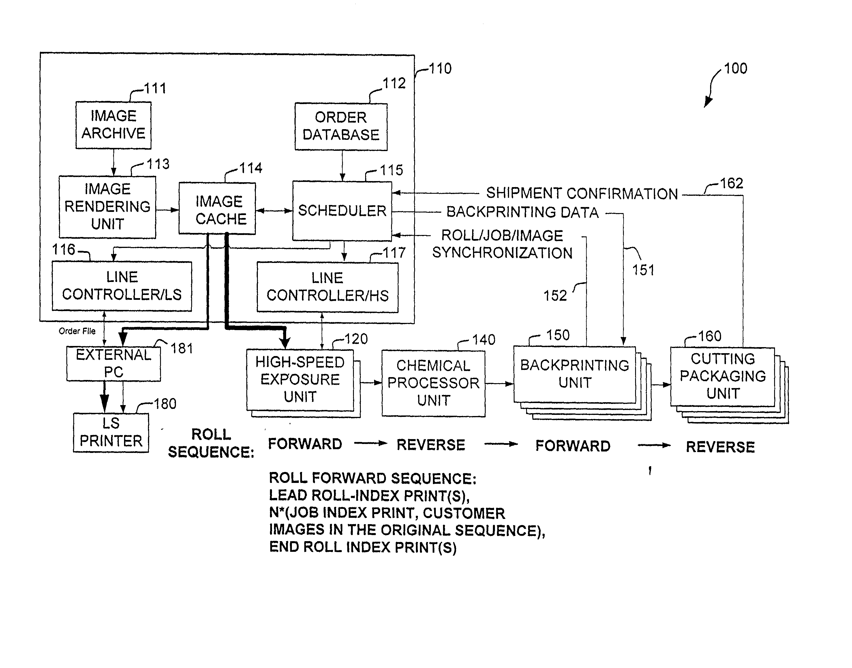
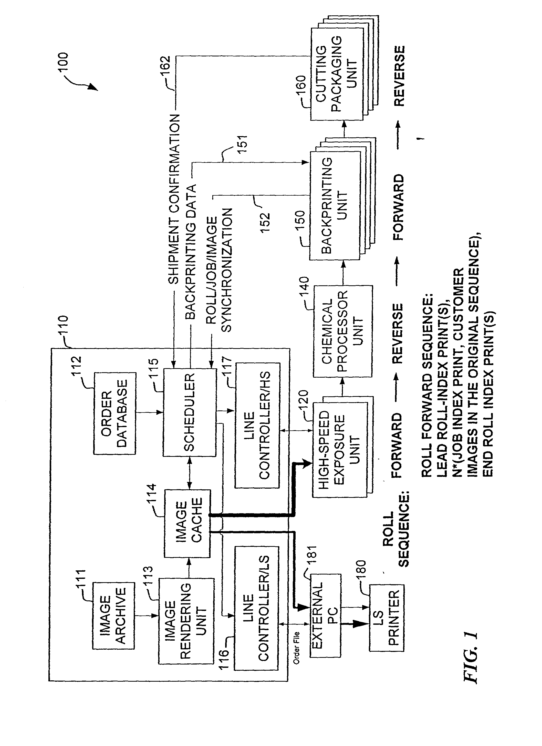
[0024] FIG. 1 shows one embodiment of the present invention, high-speed printing system 100, having a computer system 110, one or more high-speed exp...


PUM


Abstract

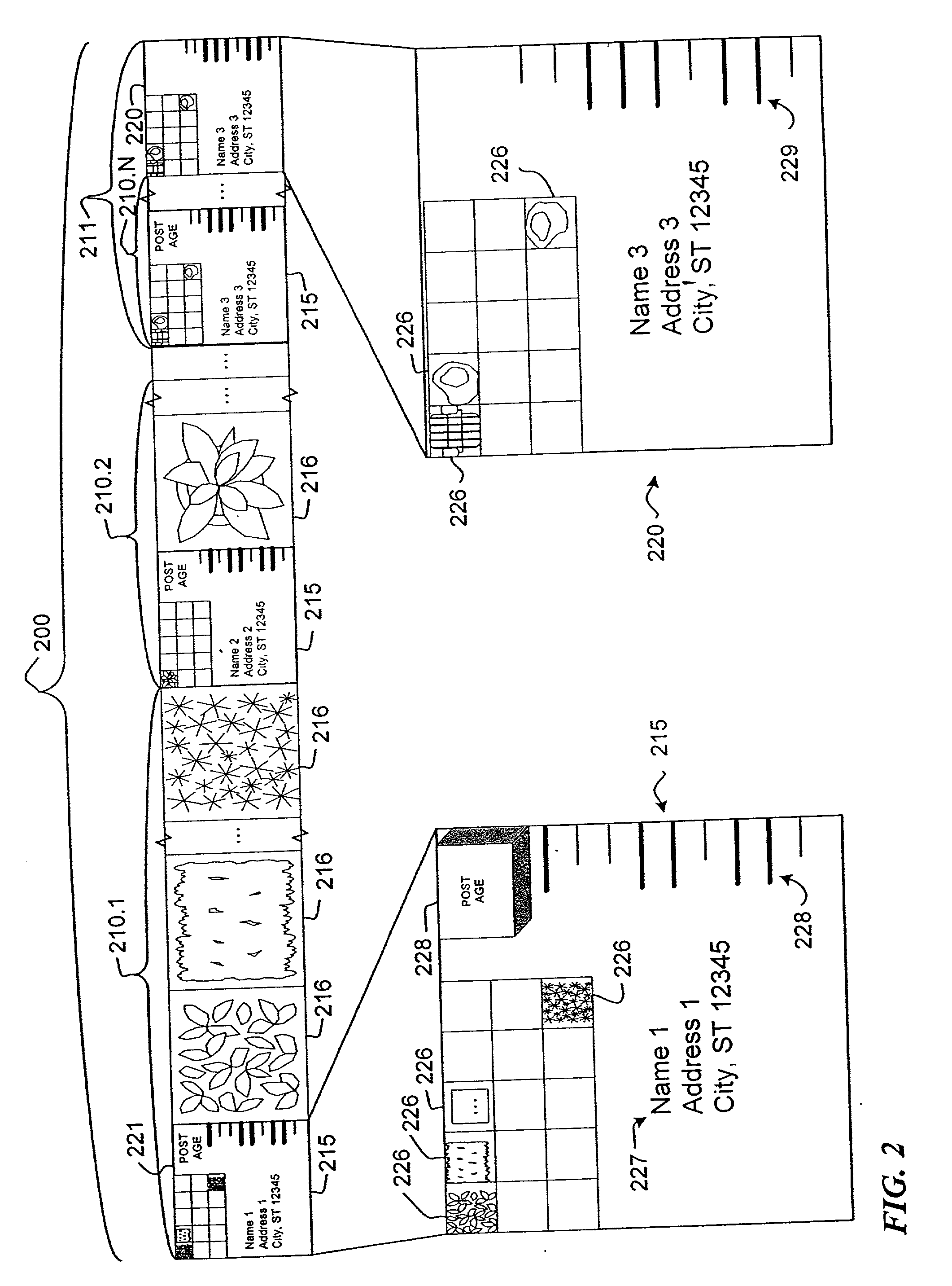
A high-speed digital photographic printing system and method includes image-specific backprinting and automatic tracking and sorting of printed jobs. The system includes one or more photographic printers, where each printer can have a different printing rate. A scheduler schedules printing orders to the different printers. The printer-independent image rendering is conducted asynchronous to the printing to maximize the printing throughput. In some embodiments, the rendering image processor does the vast majority of the image processing and outputs a printer-independent data file (generally much larger than the source image data file) that requires little if any further data manipulations or processing in the exposure unit. A photographic printing method and system for producing prints in response to input digital images includes a high-speed exposure unit that exposes a photosensitive material coated on a substrate in response to the input digital image, a chemical processor unit that receives and processes the exposed photosensitive material to form visible dye images on the substrate, a backprinting unit that receives the substrate having the visible dye images and prints information on the opposite surface of the substrate to the dye image, and a cutting unit that produces separate sheets of printed images after the backprinting unit prints information.

Description

CROSS-REFERENCES TO RELATED INVENTIONS[0001] 1. Field of the Invention[0002] This invention relates to the field of image printing, and more specifically to an apparatus, architecture and method for high-speed printing of digital image data onto a photo-sensitive substrate such as paper.[0003] 2. Background of the Invention[0004] For many years, color photographs were produced in an analog process based on silver-halide chemistry. An image was captured by exposing a photo-sensitive film to a scene by a lens system in a camera. The photo-sensitive film was developed producing a dye image on the film. A photo-sensitive paper was in turn exposed to an image formed by the dye image on the film to generate a photographic print. Lens systems can be used to enlarge the image that is printed onto the paper substrate.[0005] As with other systems, photography can benefit from digital techniques applied to various aspects of the process. However, it is still often desirable to retain certain a...

Claims


Application Information

Patent Timeline
IPC IPC(8): G03D3/00
CPCG03D3/00
Inventor BAUM, DANIELBOONE, JEFFMUZZOLINI, RUSSREDD, JARRETTSMITH, JEANNINEVORIS, JOHNWEN, XIN
Owner SHUTTERFLY LLC
Learn More