
Coupled steering gear shaft

a technology of steering gear shaft and coupling shaft, which is applied in the direction of gearing, transportation and packaging, mechanical equipment, etc., can solve the problems of reducing the operating life and efficiency of the power steering assembly, special tooling, and enhance wear, so as to reduce stress, reduce backlash, and high torsional stiffness

Active Publication Date: 2022-11-15
R H SHEPPARD
View PDF31 Cites 0 Cited by
  • Summary
  • Abstract
  • Description
  • Claims
  • Application Information

AI Technical Summary

Benefits of technology

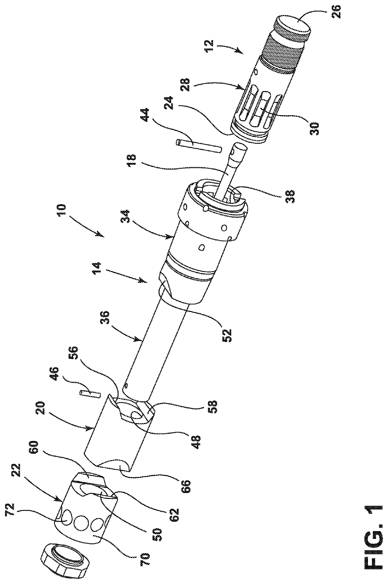
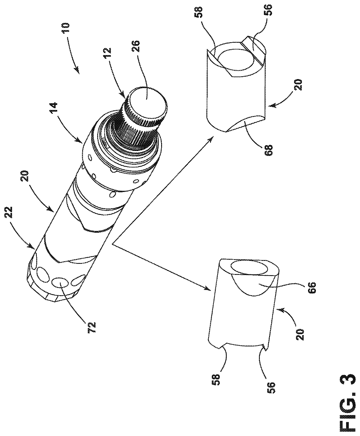
[0007]In this and other embodiments, the output shaft includes first and second inwardly-angled surfaces adapted to cooperate with the mid-coupler. The mid-coupler includes first and second extensions adapted to engage the first and second inwardly-angled surfaces of the output shaft, such that the mid-coupler is rotationally coupled to the output shaft for transferring power to the screw mechanism. The mid-coupler includes an inner diameter that is greater than an outer diameter of the output shaft, such that the mid-coupler can move laterally to maintain the smooth transfer of power between the output shaft and the screw mechanism despite potential radial and angular misalignments therebetween. In other embodiments, the mid-coupler and the screw mechanism include an inner diameter that is substantially equal to the outer diameter of the output shaft, i.e., having a tight tolerance with respect to the outer diameter of the output shaft.
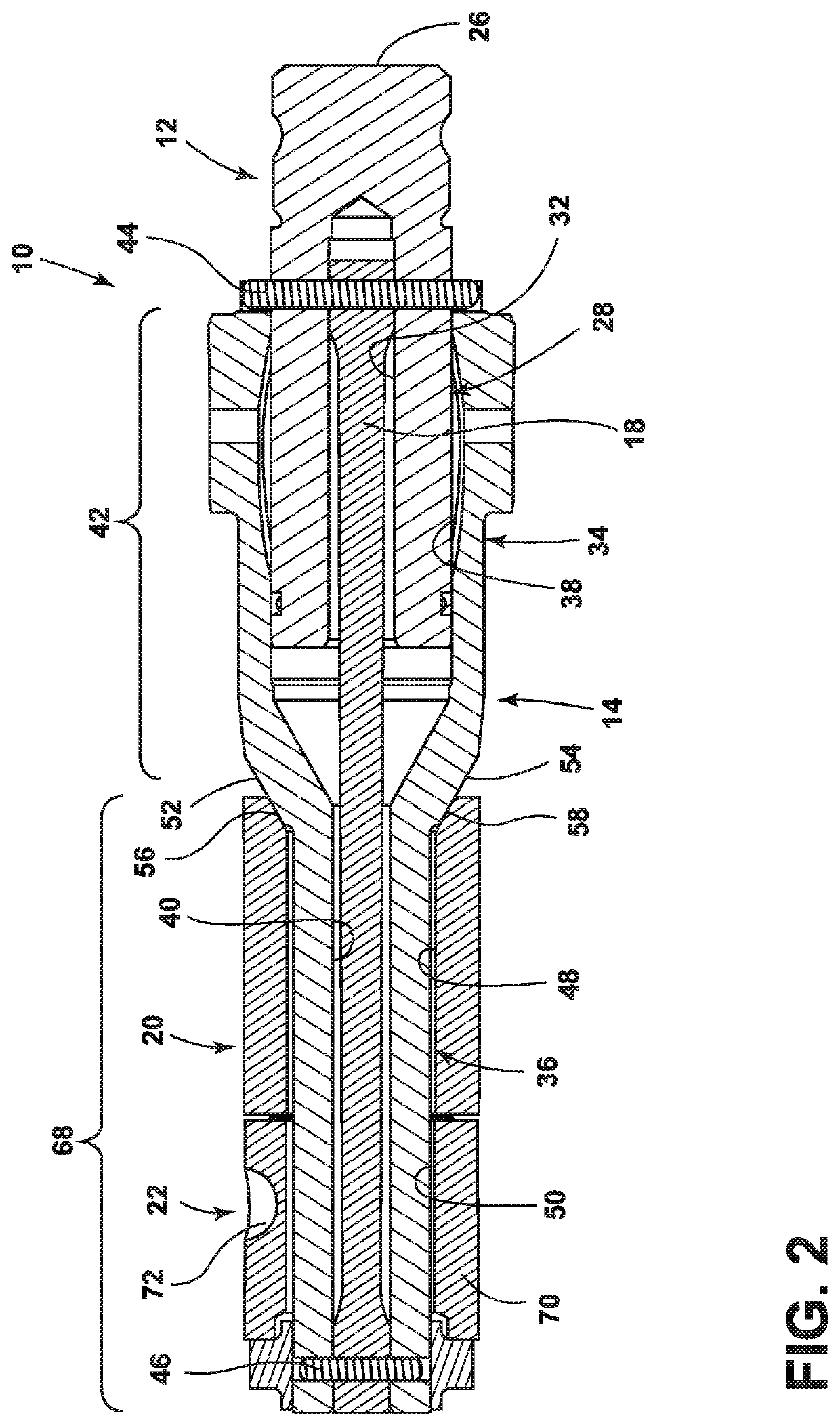
[0010]As described below, the improved steering shaft assembly can accommodate radial and angular misalignments, reduce stresses on the input shaft and control valve components, and provide minimum backlash and high torsional stiffness. In particular, the first direction of sliding of the mid-coupler relative to the output shaft and the second direction of sliding of the screw mechanism relative to the mid-coupler are perpendicular to each other. The perpendicular movement of the mid-coupler relative to the screw mechanism provides for two-axis adjustments, transverse to an axis of rotation of the control valve, to account for misalignments.

Problems solved by technology

Any misalignments in the power steering assembly will enhance wear on these seals and reduce the operating life and efficiency of the power steering assembly.
Further, conventional systems requires special tooling for each platform due to various piston travel lengths.
Any misalignment or mounting error between these components will impose side loads on the input shaft due to its high radial stiffness.
This can lead to a malfunction of the input shaft due to excessive fatigue over time.

Method used


Image

  • Coupled steering gear shaft
  • Coupled steering gear shaft
  • Coupled steering gear shaft

Examples


Embodiment Construction

[0024]Referring to FIGS. 1-3, a steering shaft assembly in accordance with one embodiment is illustrated and generally designated 10. The steering shaft assembly 10 generally includes an input shaft 12, an output shaft 14, a piston 16 (shown in FIG. 5), a torsion bar 18, a mid-coupler 20, and a ball screw mechanism 22 (referred to as a “screw mechanism” herein). The input shaft 12 is coupled to the output shaft 14 by the torsion bar 18 for transferring power between the input shaft 12 and the output shaft 14. The mid-coupler 20 is adapted to cooperate with the output shaft 14 for transferring power between the output shaft 14 and the mid-coupler 20. The screw mechanism 22 is adapted to cooperate with the mid-coupler 20 for transferring power between the mid-coupler 20 and the screw mechanism 22. The screw mechanism 22 is adapted to cause the piston 16 to move laterally relative to the output shaft 14 to convert rotation of the output shaft 14 through the mid-coupler 20 into rotation...


PUM


Abstract

An improved steering shaft assembly is provided. The steering shaft assembly further includes an output shaft that is rotatable with respect to the input shaft. The output shaft includes a rotary valve portion and a longitudinal portion. The steering shaft assembly further includes a torsion bar coupled to the input shaft and coupled to the output shaft distal from the input shaft. The steering shaft assembly further includes a mid-coupler extending around about the longitudinal portion of the output shaft and adapted to cooperate with the rotary valve portion of the output shaft. The steering shaft assembly further includes a screw mechanism extending about the longitudinal portion of the output shaft and adapted to cooperate with the mid-coupler. The screw mechanism is adapted to move laterally relative to the output shaft to maintain transfer of power from between output shaft and the screw mechanism despite misalignments therebetween.

Description

CROSS-REFERENCE TO RELATED APPLICATIONS[0001]This application claims the benefit of U.S. Provisional Application 62 / 873,420, filed Jul. 12, 2019, and U.S. Provisional Application 62 / 930,736, filed Nov. 5, 2019, the disclosures of which are incorporated by reference in their entirety.FIELD OF THE INVENTION[0002]The present invention relates to a steering shaft assembly adapted to accommodate radial and angular misalignments for power steering and other applications.BACKGROUND OF THE INVENTION[0003]Many conventional power steering assemblies include an elongated torsion bar joined to an input shaft and to an output shaft. The elongated torsion bar transfers torque applied to the input shaft (in response to rotation of a steering wheel) to the output shaft, causing the output shaft to rotate to a lesser extent than the input shaft. Rotation of the output shaft is typically converted by a recirculating ball screw into linear movement of a piston, which in turn causes rotation of a secto...

Claims


Application Information

Patent Timeline
Patent Type & Authority Patents(United States)
IPC IPC(8): F16H25/22B62D3/02
CPCF16H25/2214B62D3/02B62D5/083B62D5/24
Inventor TIPTON, JEFFREYVANTRAN, JOHNTERWAD, MANJUNATHPITZER, JARED
Owner R H SHEPPARD
Learn More