
Multi-stage amplifier circuit

Active Publication Date: 2022-11-08
RICHTEK TECH
View PDF7 Cites 0 Cited by
  • Summary
  • Abstract
  • Description
  • Claims
  • Application Information

AI Technical Summary

Benefits of technology

The solution enhances the response speed of the amplifier circuit while reducing power consumption and minimizing signal distortion, maintaining stability and improving the overall performance of the amplifier.

Problems solved by technology

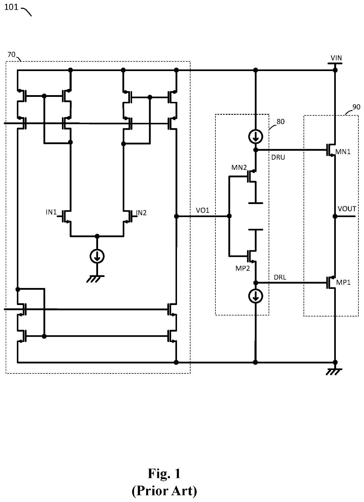
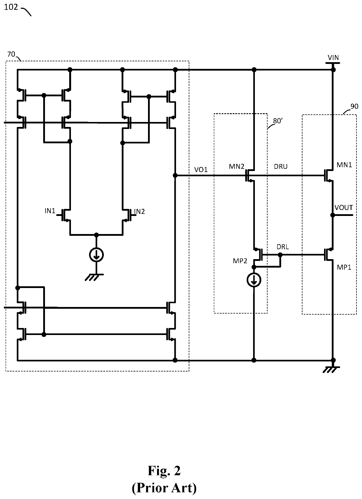
Besides, in a case where the upper transistor MN1 and the lower transistor MP1 of the output stage circuit 90 have a large size, in order to ensure stability of the multi-stage amplifier circuit, it will be required for the constant offset current of the level shifter circuit (i.e., 80 and 80′) to be high, but this will undesirably cost more power consumption.
Moreover, because the prior art multi-stage amplifier circuits 101 and 102 adopts a level shifter circuit (i.e., 80 and 80′) to cancel the gate-source voltages of the upper transistor MN1 and the lower transistor MP1, the resulted gate-source voltage mismatches will adversely affect the output common-mode range and increase the likelihood of signal distortion.

Method used


Image

  • Multi-stage amplifier circuit
  • Multi-stage amplifier circuit
  • Multi-stage amplifier circuit

Examples


Embodiment Construction

[0041]The drawings as referred to throughout the description of the present invention are for illustration only, to show the interrelations between the circuits and the signal waveforms, but not drawn according to actual scale of circuit sizes and signal amplitudes and frequencies.

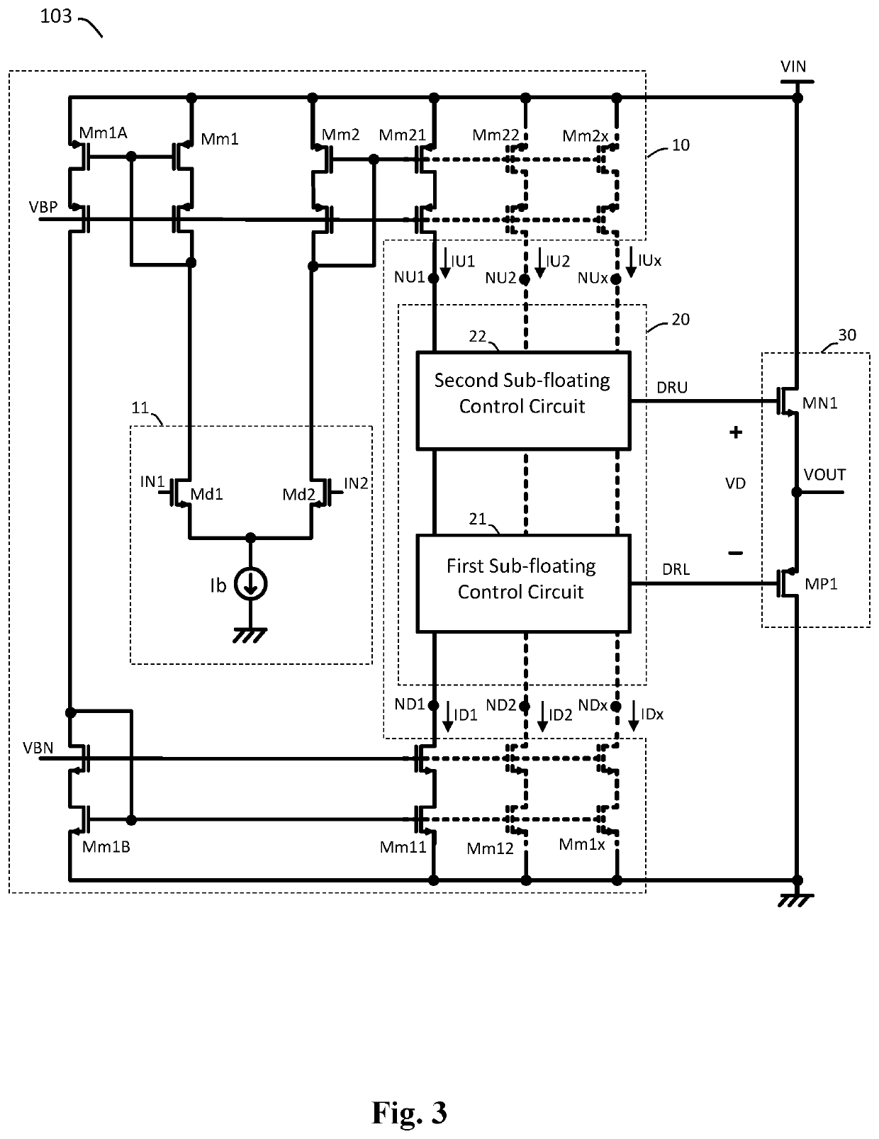
[0042]Please refer to FIG. 3, which shows a schematic diagram of a multi-stage amplifier circuit (i.e., multi-stage amplifier circuit 103) according to an embodiment of the present invention. The multi-stage amplifier circuit 103 comprises: a pre-stage amplifier 10 and a floating control circuit 20.

[0043]The pre-stage amplifier 10 is configured to operably transconduct and amplify a voltage difference between a first input terminal IN1 and a second input terminal IN2, so as to respectively generate plural corresponding pre-stage transconductance currents (i.e., pre-stage transconductance currents IU1-IUx and ID1-IDx) in plural branches through plural corresponding pre-stage transconductance nodes (i.e., pr...


PUM


Abstract

A multi-stage amplifier circuit includes a pre-stage amplifier circuit and a floating control circuit. The pre-stage amplifier circuit amplifies a voltage difference between its input terminals, to generate plural pre-stage transconductance currents flowing through corresponding plural pre-stage transconductance nodes. The floating control circuit includes: a floating reference transistor configured as a source follower and a floating amplifier. The floating amplifier and the floating reference transistor are coupled to form feedback control and to generate an upper driving signal and a lower driving signal according to a floating reference level in the floating control circuit. The upper driving signal is higher than the lower driving signal with a predetermined voltage difference. The floating control circuit is electrically connected to the plural pre-stage transconductance nodes and is floating in common mode relative to the pre-stage transconductance nodes.

Description

CROSS REFERENCE[0001]The present invention claims priority to TW 109135066 filed on Oct. 8, 2020.BACKGROUND OF THE INVENTIONField of Invention[0002]The present invention relates to an amplifier circuit; particularly, it relates to a multi-stage amplifier circuit with output stage floating control function. The present invention also relates to an output stage floating control circuit of the multi-stage amplifier circuit.Description of Related Art[0003]Please refer to FIG. 1, which shows a schematic diagram of a conventional multi-stage amplifier circuit (i.e., conventional multi-stage amplifier circuit 101). The conventional multi-stage amplifier circuit 101 includes a pre-stage amplifier 70, which is an operational transconductance amplifier. The pre-stage amplifier 70 amplifies a voltage difference between a first input terminal IN1 and a second input terminal IN2 of the pre-stage amplifier 70, to generate a pre-stage output signal VO1. Subsequently, a level shifter circuit 80 cap...

Claims


Application Information

Patent Timeline
Patent Type & Authority Patents(United States)
IPC IPC(8): H03F3/45
CPCH03F3/45269H03F2200/375H03F3/45964H03F3/45991H03F3/45192H03F2203/45301H03F2203/45308H03F2203/45124H03F3/3018
Inventor HU, MIN-HUNG
Owner RICHTEK TECH
Learn More