
Enhanced bumper system

a bumper system and bumper technology, applied in the field of bumper systems, can solve the problems of crash management systems not supporting a sufficient load, and the connection between the absorber and the cross beam is often damaged

Active Publication Date: 2022-11-01
CONSTELLIUM SINGEN GMBH
View PDF36 Cites 0 Cited by
  • Summary
  • Abstract
  • Description
  • Claims
  • Application Information

AI Technical Summary

Benefits of technology

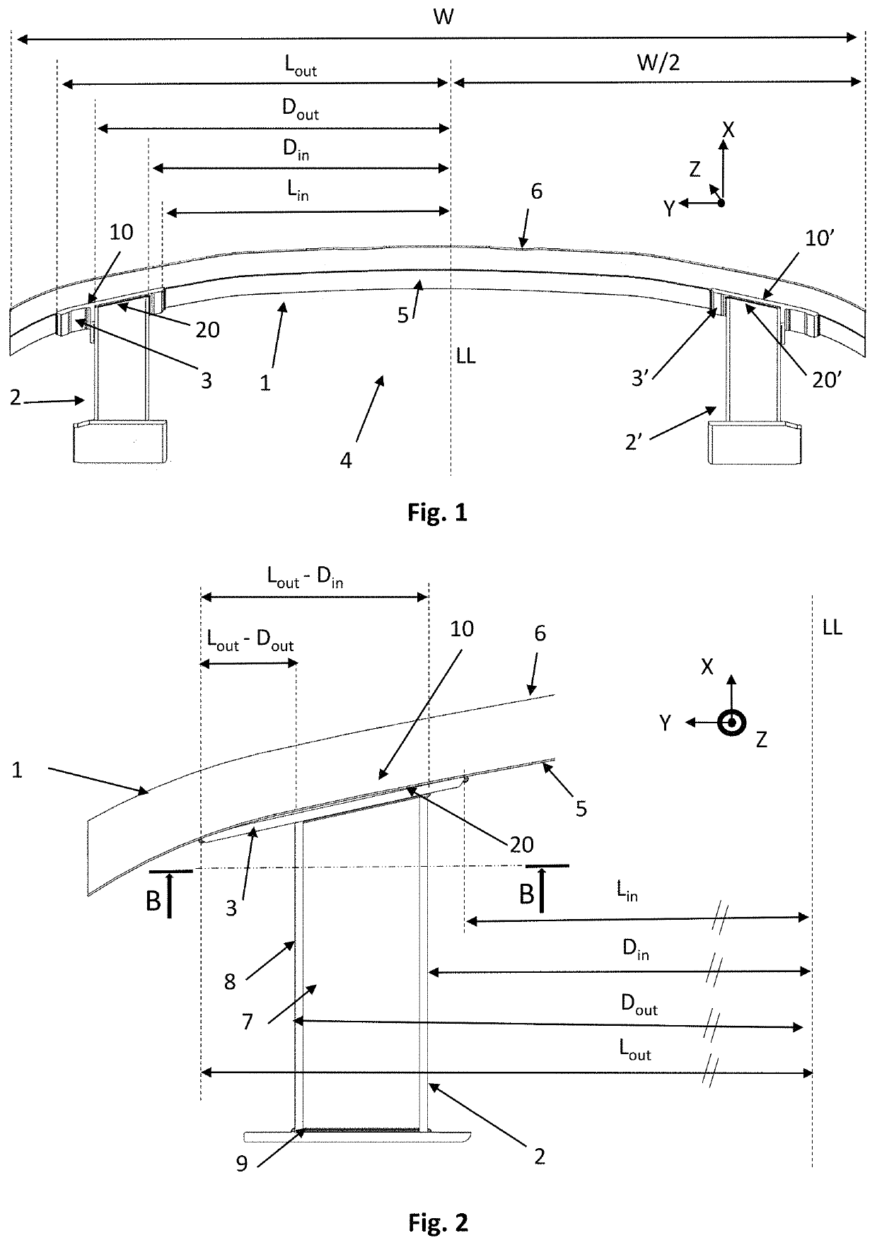
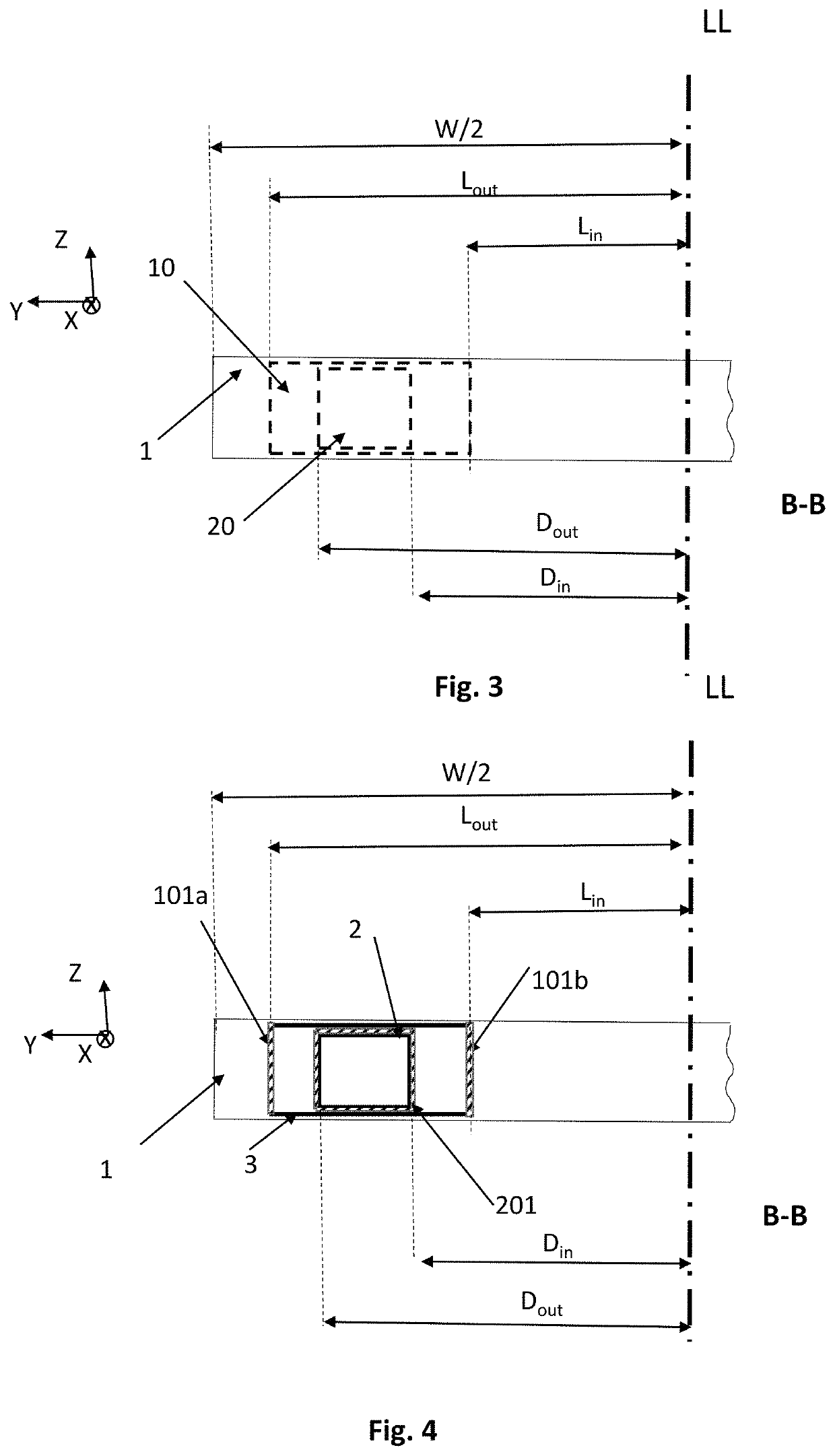
[0027]To sustain a high load impact without experiencing a premature rupture, the inventors have found that it was possible by using an intermediate component to attach the cross beam to an absorber if the intermediate component plays the role of trigger and deform before any rupture is observed. To obtain this effect, a part of the intermediate component distant from the longitudinal axis (LL) by a distance comprised between Lout and Dout has a smaller bending stiffness (Sinterm) about the vertical axis (Z) than a part of the cross beam distant from the longitudinal axis (LL) by a distance comprised between Lout and Din (Scross), said vertical axis (Z) being perpendicular to the transverse direction (X) and the longitudinal axis (LL).
[0033]The lower bending stiffness, i.e. added bending compliance, of the intermediate component reduces the stiffness of the connection between the cross beam and the absorber against a bending moment around z-axis. During a bending load, applied on the front wall of the cross-beam, the compliance of the intermediate component leads to a reduced applied load on the connection technology between the crossbeam and the absorber and permits to avoid the rupture and to sustain the load impact.
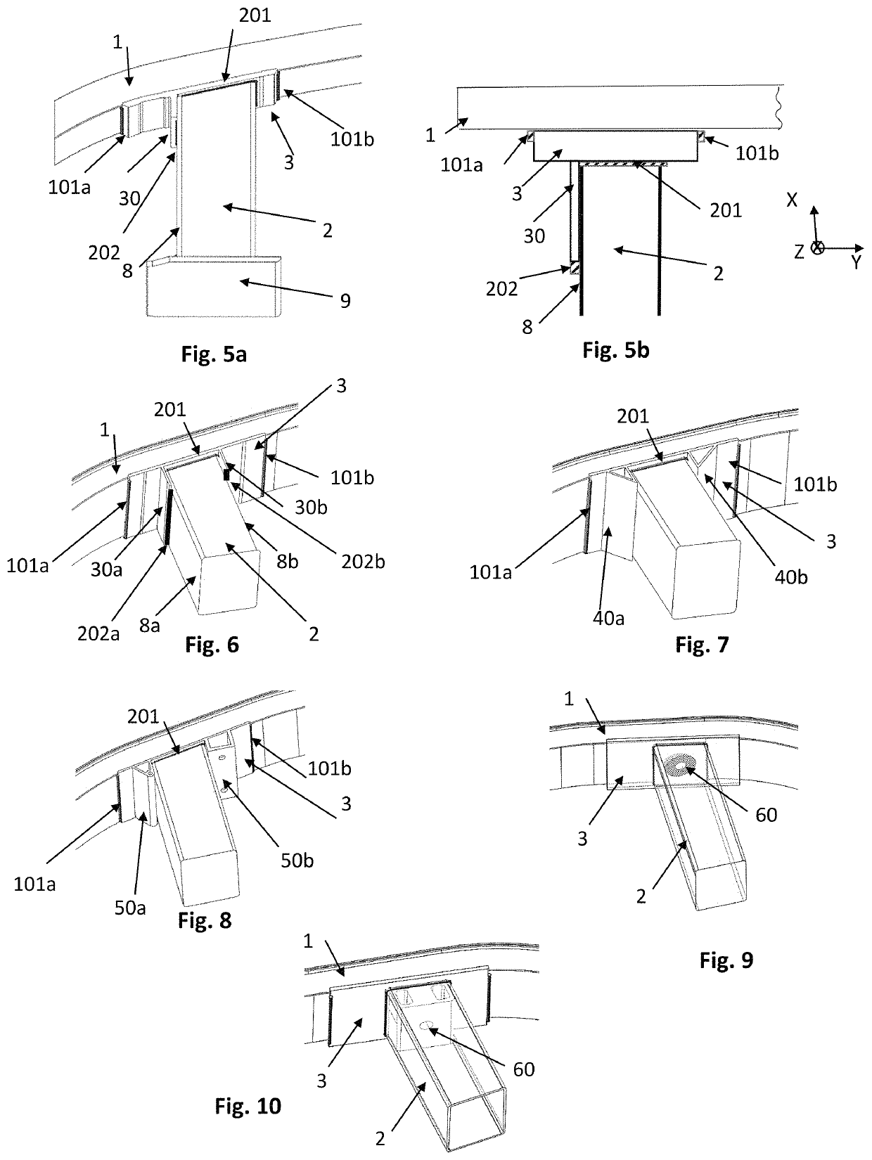
[0040]Preferably, the intermediate component comprises at least one flange, connected to at least one outer wall of the absorber. It permits to improve the shearing resistance of the assembly between the cross beam, the intermediate component and the absorber.

Problems solved by technology

If the cross beam is configured with a high bending stiffness, cracks often occurs at the connection between the absorber and the cross beam.
In particular, when the absorber is directly welded to the bumper cross beam, crack occurs in the heat affected zone and the crash management systems does not sustain a sufficient load.

Method used


Image

  • Enhanced bumper system
  • Enhanced bumper system
  • Enhanced bumper system

Examples


example

[0077]A RCAR bumper barrier test and a pole barrier test on a bumper system have been executed on two types of bumper system: a first bumper system, represented at FIG. 13 corresponding to prior art, i.e. without an intermediate component and a second bumper system represented at FIG. 14 corresponding to the invention. For both configurations, the same geometry of cross beam with three chambers, represented on FIG. 16, has been used with a total length of 1300 mm. The same absorbers, represented on FIG. 17, has been used and are positioned symmetrically around the longitudinal axis LL at a distance of 430 mm (see FIG. 15). The bumper system for both configurations is made in aluminium alloy, having a young modulus of 70 GPa.

[0078]According to the prior art, the absorbers are welded directly to the cross beam. According to the invention, an intermediate component with a flange, made in aluminium alloy with a young modulus of 70 GPa and represented on FIG. 14 is placed between the cro...


PUM


Abstract

A bumper system (4) for a motor vehicle comprising a cross beam (1) which is globally orientated in a transverse direction (Y), said cross beam comprising a front wall (6) adapted to receive a crash impact force and a rear wall (5) opposed and spaced from said front wall, at least one absorber (2), at least an intermediate component (3) to attach the absorber (2) to the cross beam (1), said intermediate component (3) being connected to the rear wall (5) through a first contact area (10), distant from a longitudinal axis (LL), by an internal component distance, called Lin, and an external component distance, called Lout, which corresponds respectively to the minimum and maximum distance between said first contact area (10) and the longitudinal axis (LL), said longitudinal axis (LL) passing at mid width of the cross beam and being perpendicular to the transverse direction (Y), said intermediate component (3) being connected to the absorber (2) through a second contact area (20) distant from the longitudinal axis (LL) by an internal profile distance, called Din, and an external profile distance, called Dout, which corresponds respectively to the minimum and maximum distance between the second contact (20) area and the longitudinal axis (LL), wherein a part of the intermediate component distant from the longitudinal axis (LL) by a distance comprised between Lout and Dout has a smaller bending stiffness (Sinterm) about a vertical axis (Z) than a part of the cross beam distant from the longitudinal axis (LL) by a distance comprised between Lout and Din (Scross), said vertical axis (Z) being perpendicular to the transverse direction (Y) and the longitudinal axis (LL).

Description

FIELD OF THE INVENTION[0001]The present invention relates to a bumper system for a motor vehicle including an intermediate component between an absorber and a cross beam to improve its ability to sustain crash impact without rupture.BACKGROUND OF THE INVENTION[0002]A bumper system permits to minimize damage or injury by absorption of energy through elastic and, eventually, plastic deformation during frontal and rear collisions with pedestrians, other vehicles and fixed obstacles.[0003]Generally, a bumper system for motor vehicle comprises a cross beam which is attached to supports remote from each other, such as absorber or crash boxes, and located in continuation of the longitudinal frame members of the motor vehicle.[0004]For example, US20160297387 of Benteler discloses a bumper arrangement for a motor vehicle, including a cross member made of a lightweight metal and constructed as multi-chamber section; and crash boxes arranged in respective end regions of the cross member for co...

Claims


Application Information

Patent Timeline
Patent Type & Authority Patents(United States)
IPC IPC(8): B60J7/00B60R19/34B60D1/56B60R19/18
CPCB60R19/34B60D1/56B60R2019/1813B60Y2410/124B60Y2410/125B60Y2300/28
Inventor WIEDEMANN, JOCHENSCHMID, THOMASKLEINDICK, TIM
Owner CONSTELLIUM SINGEN GMBH
Learn More