
Battery

a rechargeable battery and battery pack technology, applied in the field of batteries, can solve the problems of battery open-circuit potential decline, problem of parallel recharging, and bulky size of battery packs

Active Publication Date: 2022-10-25
GP TECH & INNOVATION LTD
View PDF43 Cites 0 Cited by
  • Summary
  • Abstract
  • Description
  • Claims
  • Application Information

AI Technical Summary

Problems solved by technology

However, such battery packs are typically bulky in size due to the need to provide internal electrical connections between the conventional rechargeable batteries within the battery pack housing and to provide the housing with externally accessible electrical terminals or connectors.
Where the conventional rechargeable batteries are electrically connected in parallel within the battery pack, problems can occur with parallel recharging.
One problem with recharging batteries in parallel is that a battery's open-circuit potential decreases as its temperature increases.
This in turn can cause further warming and a yet lower open-circuit potential, thereby setting up a positive feedback loop.
Such a positive feedback loop may result in a large imbalance in the charging current distribution between the batteries in the pack and may lead to overcharging and consequent damage in some of the batteries.
This is a particular issue with Nickle-based batteries such as NickleMetal Hydride (NIMH) batteries.
However, laser welding onto an end of an electrode layer presents many challenges and can lead to damage of the electrode assembly separator layer.
A problem with this battery arrangement is that any movement of the plurality of electrode assemblies within the can may fatigue the lead tabs and eventually lead to breakage of one or more of said lead tabs.
Furthermore, the leads tabs limit the size and efficiency of conducting pathways from the electrode layers of the electrode assemblies to their respective current collecting plates.

Method used


Image

  • Battery
  • Battery
  • Battery

Examples


first embodiment

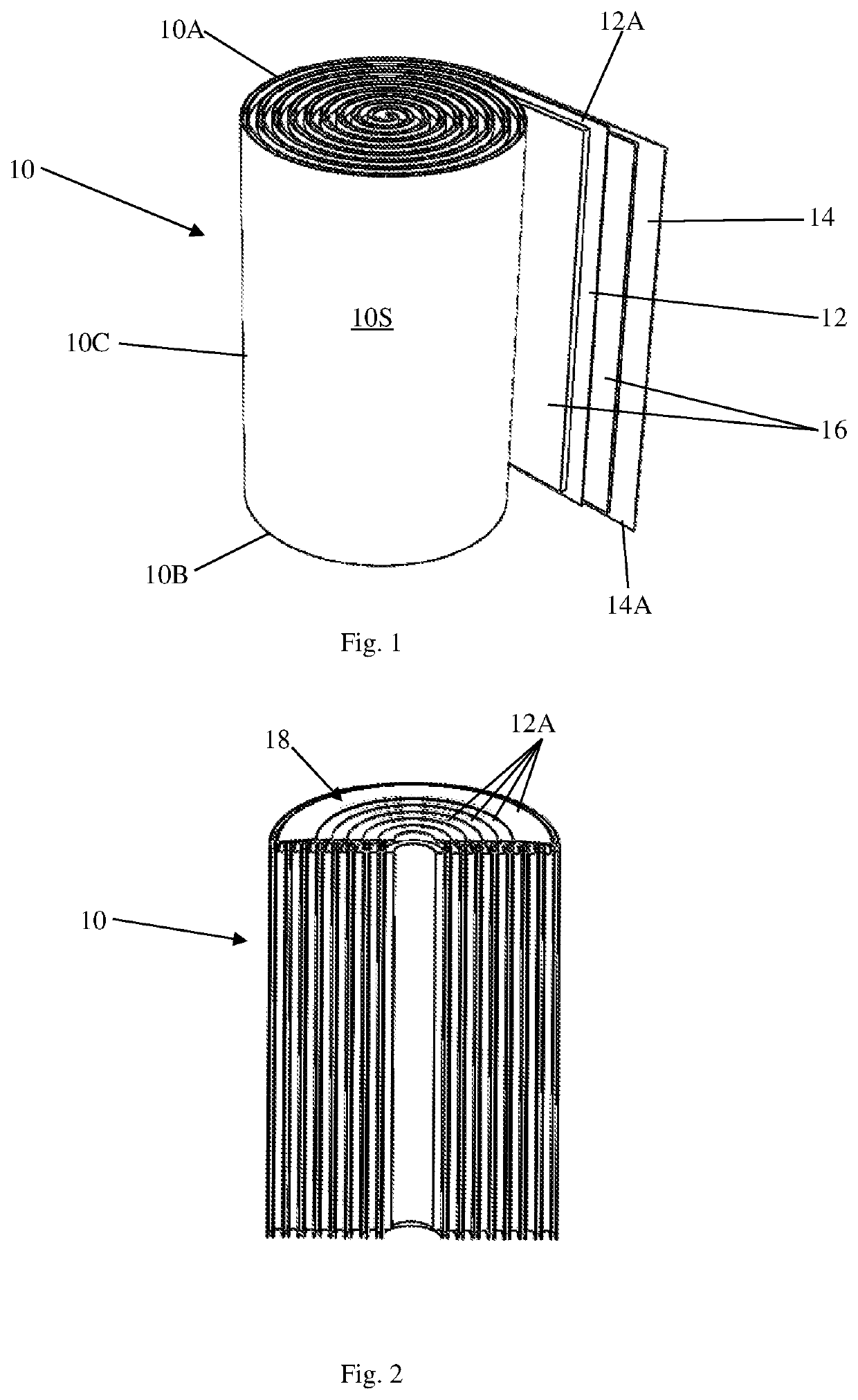
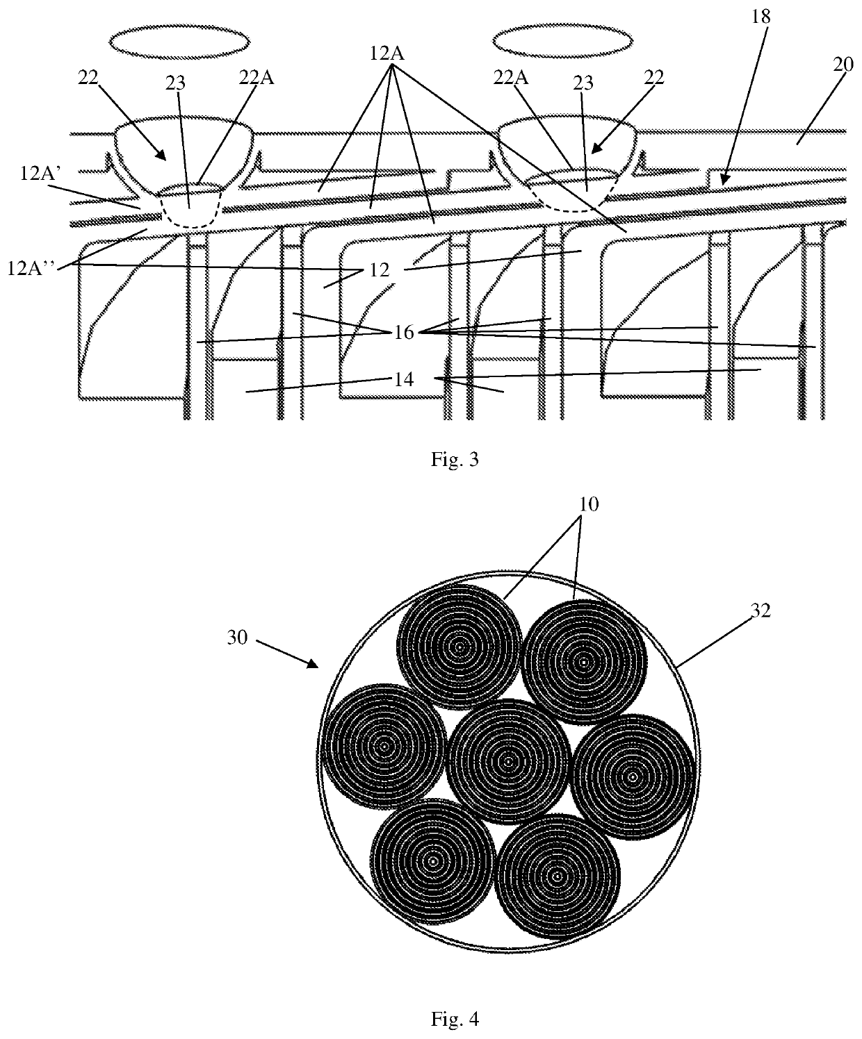
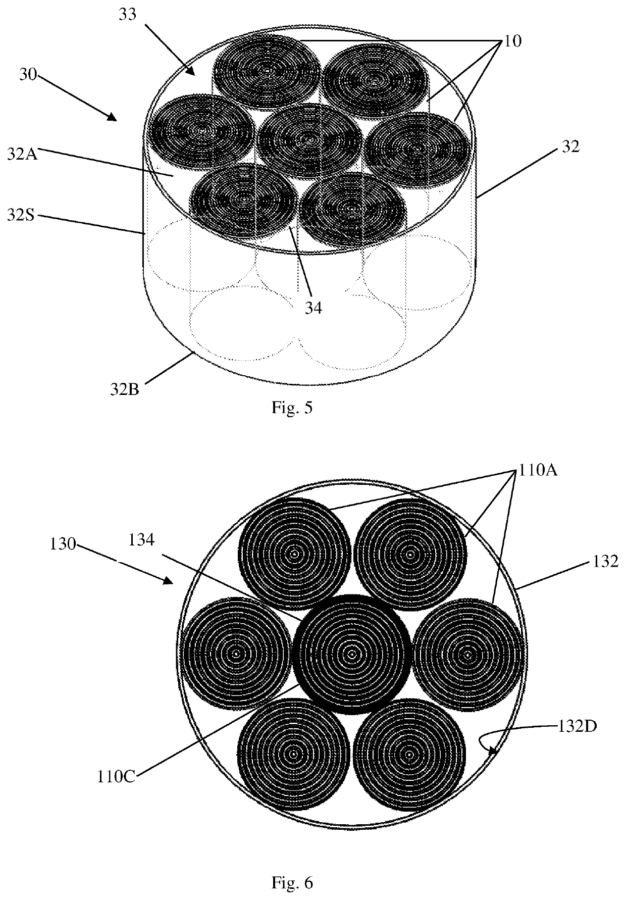
[0049]Referring to FIGS. 4 and 5, shown are a plan view and a perspective view of a battery housing 32 showing one arrangement of a plurality of electrode assemblies 10 for a high capacity battery 30 in accordance with the invention. The battery assemblies 10 may each comprise a jelly roll 10 in accordance with that described with respect to FIGS. 1 to 3. The plurality of electrode assemblies 10 is preferably arranged substantially in parallel with each other within the single battery housing 32. In this embodiment, the battery housing 32 comprises a battery can 32. The battery can 32 is substantially cylindrical in shape with an upper open end 32A and a lower closed end 32B. At least the closed end 32B of the battery can 32 is preferably formed of an electrically conductive material such that said closed end 32B forms, in use, a negative terminal for the battery 30. A side wall 32S of the can 32 surrounds a battery compartment 33 preferably defining a single shared volume for recei...

second embodiment

[0056]Referring to FIGS. 6 and 7, shown are a plan view and a perspective view of a battery can 132 showing another arrangement of a plurality of electrode assemblies 110 for a high capacity battery 130 in accordance with the invention. Once again, the battery electrode assemblies 110 may each comprise a jelly roll 110 in accordance with that described with respect to FIGS. 1 to 3. The plurality of electrode assemblies 110 is arranged substantially in parallel with each other within the single battery can 132. A current collector plate (not shown) is arranged to be directly electrically in contact with the first ends of the plurality of electrode assemblies 110.

[0057]The current collector plate may be directly electrically in contact or in connection with the first ends of the plurality of electrode assemblies 110 by the same or similar means described with respect to the embodiment of FIGS. 4 and 5.

[0058]In FIGS. 6 and 7, it can be observed that the plurality of electrode assemblie...

third embodiment

[0061]Referring to FIGS. 8 and 9, shown are a plan view and a perspective view of a battery can 232 showing another arrangement of a plurality of electrode assemblies 210 for a high capacity battery 230 in accordance with the invention. Once again, the battery assemblies 210 may each comprise a jelly roll 210 in accordance with that described with respect to FIGS. 1 to 3. The plurality of electrode assemblies 210 is arranged substantially in parallel with each other within the single battery can 232. A current collector plate (not shown) is arranged to be directly electrically in contact with the first ends of the plurality of electrode assemblies 210.

[0062]The current collector plate may be directly electrically in contact or in connection with the first ends of the plurality of electrode assemblies 210 by the same or similar means described with respect to other embodiments.

[0063]In FIGS. 8 and 9, it can be observed that the plurality of jelly rolls 210 is arranged within the can ...


PUM

PropertyMeasurementUnit
heightaaaaaaaaaa
pressureaaaaaaaaaa
electricalaaaaaaaaaa

Abstract

A battery (30) is disclosed which comprises: a housing (32) containing an electrolyte solution; a plurality of jelly roll electrode assemblies (10) arranged substantially in parallel with each other in contact with the electrolyte solution within the housing (32) thereby forming a single electrochemical system of the battery (30), each jelly roll electrode assembly (10) having a first end (10A) and an opposing second end (10B); and a current collector plate (20); wherein the current collector plate (20) is arranged to be shared among and in direct physical and electrical contact with the first ends (10A) of the plurality of jelly roll electrode assemblies (10).

Description

CROSS-REFERENCE TO RELATED APPLICATION[0001]This application is a 371 application of PCT application no. PCT / CN2019 / 098278 filed Jul. 30, 2019, which claims priority from a U.K. patent application no. 1812381.0 filed Jul. 30, 2018, and the disclosures of which are incorporated herein by reference in their entirety.TECHNICAL FIELD[0002]The invention relates to a battery, and more particularly, although not exclusively, to a high capacity, rechargeable battery.BACKGROUND ART[0003]Typically, to form a high capacity, rechargeable battery unit, a number of conventional rechargeable batteries are electrically connected in parallel or series and typically enclosed in a housing to provide a single rechargeable battery pack. However, such battery packs are typically bulky in size due to the need to provide internal electrical connections between the conventional rechargeable batteries within the battery pack housing and to provide the housing with externally accessible electrical terminals o...

Claims


Application Information

Patent Timeline
Patent Type & Authority Patents(United States)
IPC IPC(8): H01M50/538H01M50/186H01M50/528H01M50/536H01M10/04H01M10/28H01M10/30
CPCH01M50/538H01M10/0422H01M10/0431H01M10/286H01M10/30H01M50/186H01M50/528H01M50/536Y02E60/10Y02P70/50H01M50/107H01M50/477H01M50/609H01M50/48H01M50/559H01M50/152H01M50/184
Inventor TSANG, HING POTANG, PING HUNGLUK, YUEN HAN
Owner GP TECH & INNOVATION LTD
Learn More