
Organic light emitting diode display panel and display device

a light-emitting diode and display panel technology, applied in the field of display technologies, can solve the problems of difficult to meet the compensation requirements difficult to make the display brightness of the bending area and the display brightness of the non-bending area uniform, and the brightness of the display panel will change significantly

Active Publication Date: 2022-10-04
WUHAN CHINA STAR OPTOELECTRONICS SEMICON DISPLAY TECH CO LTD
View PDF18 Cites 0 Cited by
  • Summary
  • Abstract
  • Description
  • Claims
  • Application Information

AI Technical Summary

Benefits of technology

The present patent provides an OLED display panel and a display device that compensates for threshold voltage of remaining display frames using different pixel drive circuits for bending and non-bending areas. This results in uniform brightness across the entire display panel and meets compensation range requirements in the bending area. The duration of the compensation time for the bending area is longer, so a larger compensation voltage range can be achieved.

Problems solved by technology

Due to a short compensation time, a compensation range is only about plus / minus 0.5 v, which makes it difficult to meet compensation requirements of the bending area.
Therefore, it is difficult to make a display brightness of the bending area and a display brightness of the non-bending area uniform.
In the bending area, the brightness of the display panel will change significantly, and the current compensation method cannot completely eliminate a brightness difference.
Accordingly, the existing OLED display panel has a technical problem that the brightness of the bending area is different from that of the non-bending area, which needs to be improved.

Method used


Image

  • Organic light emitting diode display panel and display device
  • Organic light emitting diode display panel and display device
  • Organic light emitting diode display panel and display device

Examples


Embodiment Construction

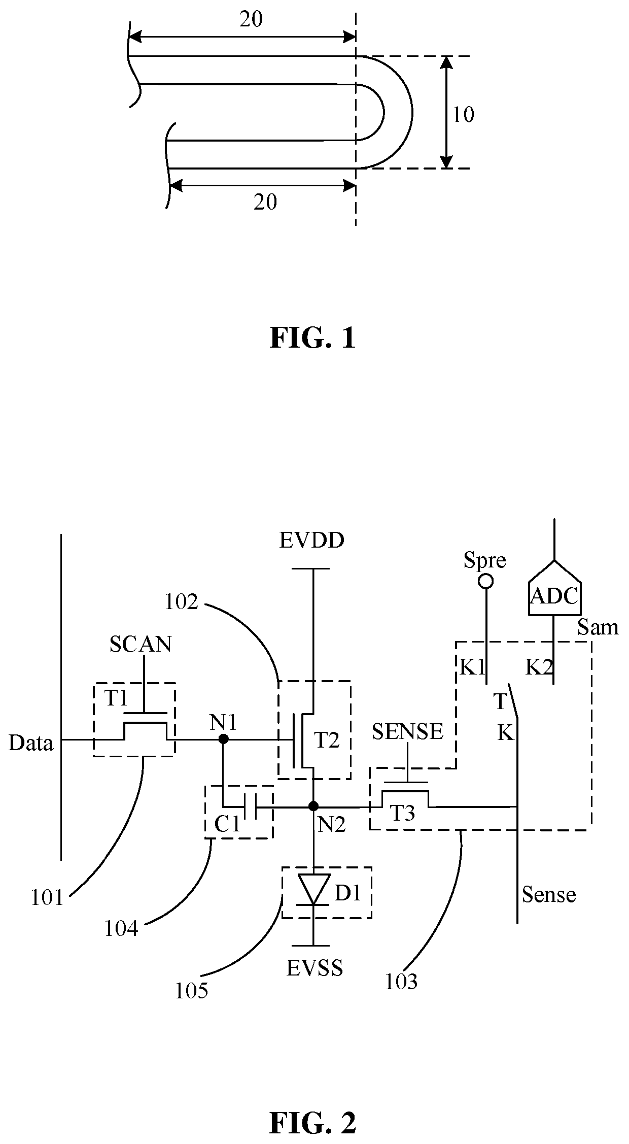
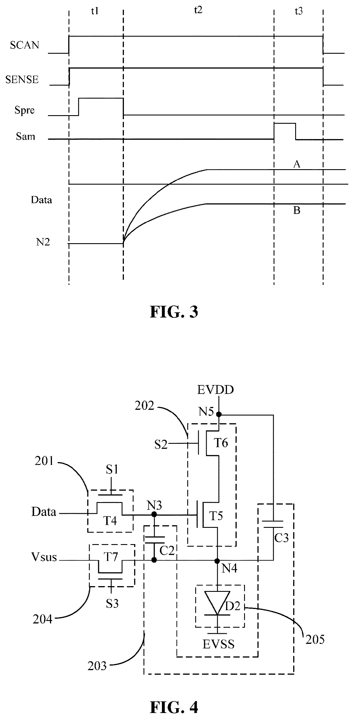
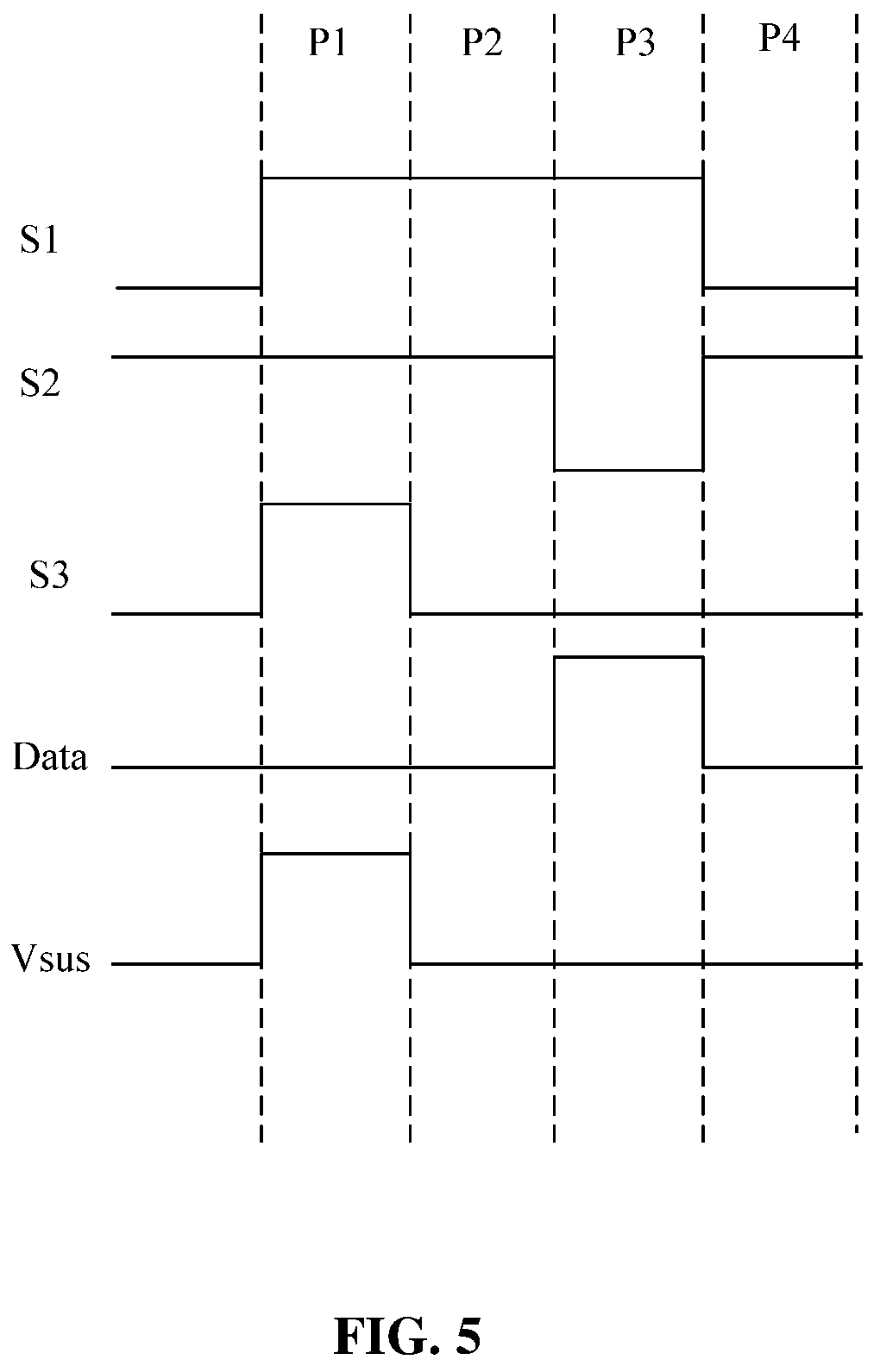
[0039]The following embodiments are referring to the accompanying drawings for exemplifying specific implementable embodiments of the present disclosure. Furthermore, directional terms described by the present disclosure, such as upper, lower, front, back, left, right, inner, outer, side and etc., are only directions by referring to the accompanying drawings, and thus the used directional terms are configured to describe and understand the present disclosure, but the present disclosure is not limited thereto.

[0040]An embodiment of the present disclosure provides an OLED display panel and a display device to solve a technical problem of different brightness of a bending area and a non-bending area in an existing OLED display panel.

[0041]The present disclosure provides an OLED display panel, including a bending area and a non-bending area. The OLED display panel further includes a first pixel driving circuit and second pixel driving circuit.

[0042]The first pixel driving circuit is con...


PUM

PropertyMeasurementUnit
threshold voltageaaaaaaaaaa
time periodaaaaaaaaaa
timeaaaaaaaaaa

Abstract

An organic light emitting diode (OLED) display panel and a display device are provided. A first pixel driving circuit of the is configured to compensate a threshold voltage of a drive transistor in the bending area during a first time period before starting up or a second time period after shutting down. A second pixel driving circuit is configured to compensate a threshold voltage of a drive transistor in the non-bending area during a blank time period between adjacent display frames. A duration of the first time period and a duration of the second time period are both greater than a duration of the blank time period. A brightness of the display panel is uniform.

Description

FIELD OF DISCLOSURE[0001]This present disclosure relates to the field of display technologies, and in particular to an organic light emitting diode (OLED) display panel and a display device.BACKGROUND[0002]In existing active-matrix organic light emitting diode (AMOLED) display panels, a threshold voltage Vth of a transistor will drift due to various reasons, so the threshold voltage Vth needs to be compensated by a pixel driving circuit. For a small-sized foldable display panel, due a bending area is subject to stress changes for a long time, a threshold voltage Vth of each transistor in the bending area is very prone to change, and the change is greater than that in a non-bending area. A voltage range required for compensation is also larger. The pixel driving circuit currently adopted is internal compensation, and the threshold voltage Vth is compensated during a blank time period between display frames. Due to a short compensation time, a compensation range is only about plus / min...

Claims


Application Information

Patent Timeline
Patent Type & Authority Patents(United States)
IPC IPC(8): G09G3/3233G09G3/00
CPCG09G3/3233G09G3/035G09G2300/043G09G2300/0842G09G2300/0852G09G2300/0861G09G2310/0251G09G2310/08G09G2320/0233G09G2320/045G09G3/3208G09F9/301
Inventor CAI, ZHENFEI
Owner WUHAN CHINA STAR OPTOELECTRONICS SEMICON DISPLAY TECH CO LTD
Learn More