
Laser processing head for laser-wire build-up welding

a laser-wire and processing head technology, applied in welding apparatus, metal-working equipment, manufacturing tools, etc., can solve the problems of prone to errors, difficult alignment of laser beams and in particular optical fibers, and large investmen

Active Publication Date: 2022-09-27
FRAUNHOFER GESELLSCHAFT ZUR FOERDERUNG DER ANGEWANDTEN FORSCHUNG EV
View PDF15 Cites 0 Cited by
  • Summary
  • Abstract
  • Description
  • Claims
  • Application Information

AI Technical Summary

Benefits of technology

The invention provides a device for optical adjustment of a laser beam in relation to wire-shaped material, even during continuous operation. The device includes an optics carrier element that can be adjusted in two perpendicular axes using adjusting elements with threads. The adjusting elements can be manually or motorized, and the accuracy of the adjustment can be increased by using threads with a high level of self-locking. The device also includes external wire feeds with motorized drives for feeding the wire-shaped material. The wire-shaped material can be conveyed from the external wire feed to the internal wire feed and from there through the outlet nozzle without being exposed to laser radiation.

Problems solved by technology

In doing so, this results in a considerable outlay since an optical adjustment must be carried out at a plurality of positions and elements of a laser processing head that are separate from one another.
In particular, the alignment of the laser beam and in particular of an optical fiber is problematic and prone to errors during the operation or when put into operation again.

Method used


Image

  • Laser processing head for laser-wire build-up welding
  • Laser processing head for laser-wire build-up welding
  • Laser processing head for laser-wire build-up welding

Examples


Embodiment Construction

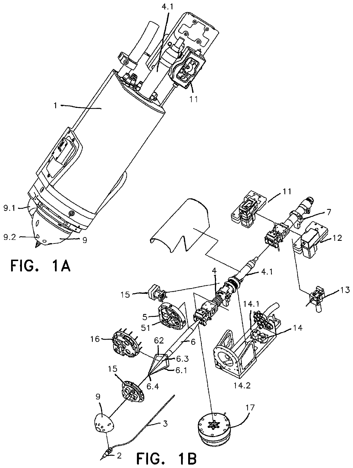
[0036]In FIGS. 1A and 1B, an example of a laser processing head according to the invention is shown. Here, an internal wire feed 2 for feeding wire-shaped material 3, optical components 4 for shaping a laser beam 6, and an optics carrier element 5.1 for deflecting the laser beam 6 and splitting the laser beam into three partial beams 6.1-6.3 are arranged in a housing 1.

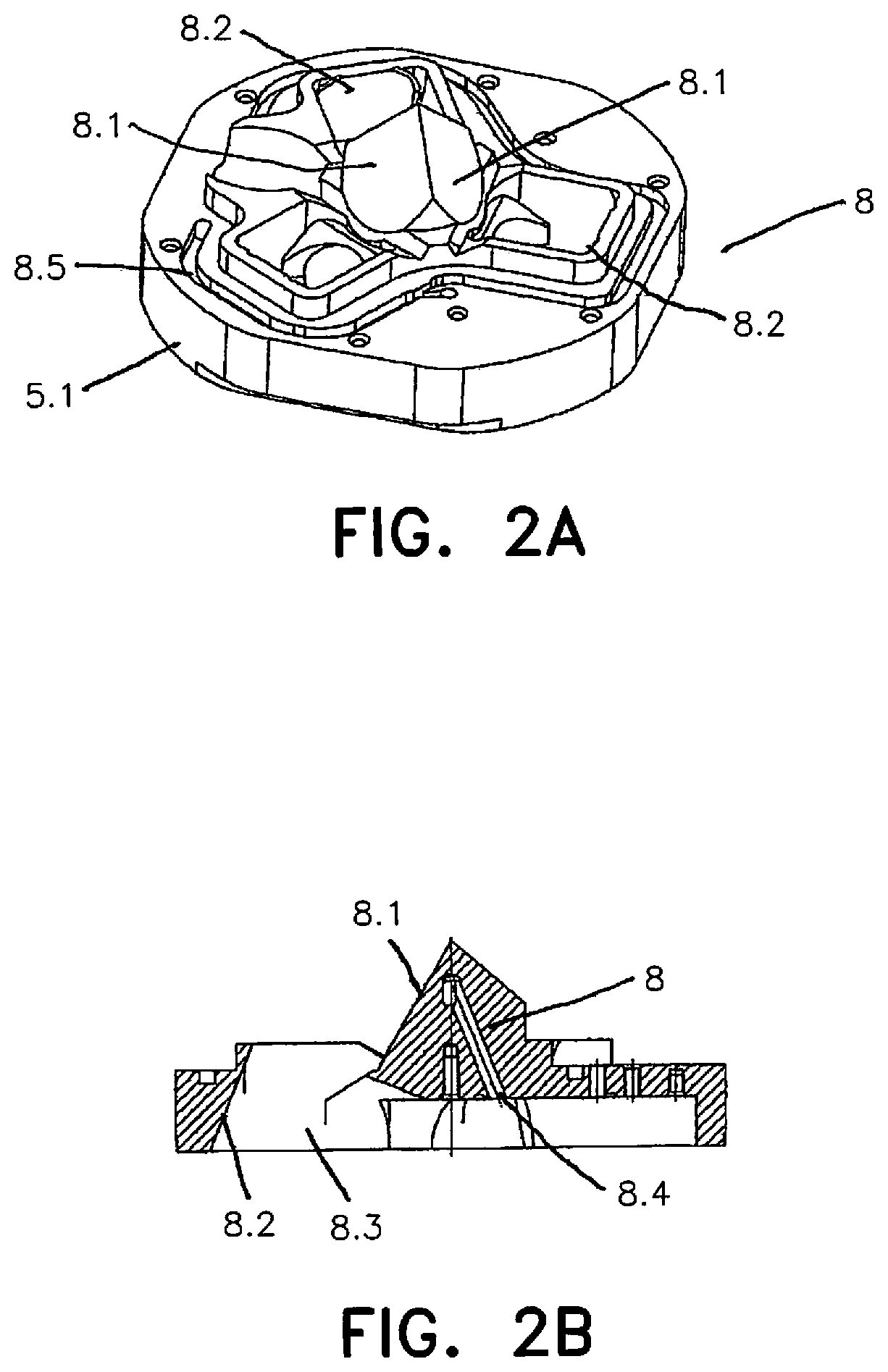
[0037]An optical unit 4 for an optical fiber 4.1 is fastened to the housing 1, through which unit the laser beam 6 is directed onto reflecting surfaces 8.1 of a pyramid-shaped element 8 and reflecting surfaces 8.2 that are formed at an optics carrier element 5.1.

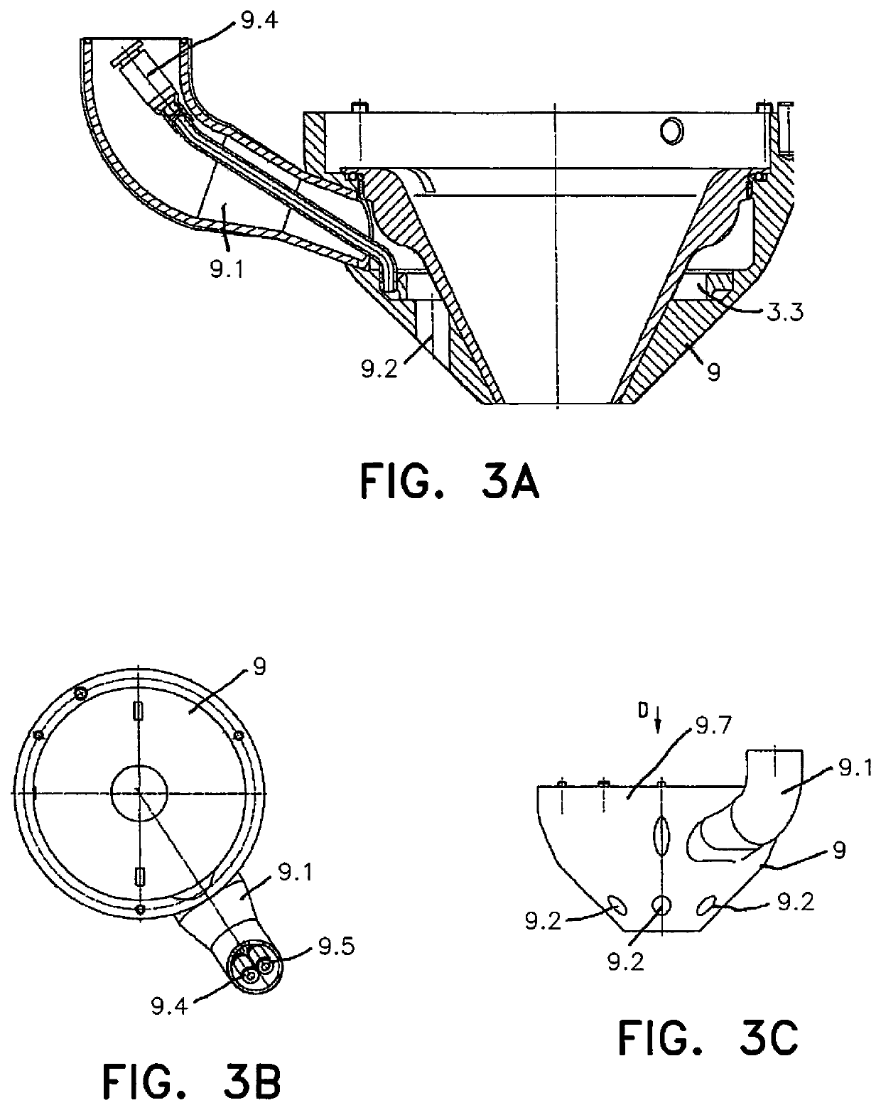
[0038]At the opposite end side of the laser processing head, a smoke extractor 9 is present, having a screw-on cone 9.7 with an opening through which the wire-shaped material 3 can be fed into the area of influence of the partial beams 6.1-6.3 intersecting in a plane, in the direction of a workpiece, not shown. A extraction channel 9.1 is present at the cone 9...


PUM

PropertyMeasurementUnit
angular distancesaaaaaaaaaa
energyaaaaaaaaaa
outer circumferenceaaaaaaaaaa

Abstract

A laser beam is directed onto a pyramid-shaped element, wherein the beam is directed onto at least three reflecting surfaces and the respective reflected partial beams are incident on reflecting surfaces arranged on an optics carrier element. The partial beams are aligned such that they intersect in a common plane. An internal wire feed is arranged in a housing, having an outlet nozzle for a fusible wire-shaped material, which material is using the energy of the partial beams. The outlet nozzle is arranged in front of the plane in which the reflected partial beams intersect. The pyramid-shaped element and the reflecting surfaces are formed on a carrier element, which is arranged in such a way that it is displaceable following the outlet nozzle in two perpendicular directions to the optical axis of the laser beam or perpendicular to the central longitudinal axis of the wire-shaped material.

Description

BACKGROUND OF THE INVENTION[0001]The invention relates to a laser processing head which is formed for laser wire build-up welding. Using the laser processing head, different wire-shaped materials, in particular wires with outer diameters of less than 1.6 mm, preferably of less than 1 mm and generally of less than 0.6 mm, can be processed. In this way, coatings or three-dimensional contours on workpiece surfaces, as well as additive manufacturing of three-dimensional workpieces or components, can be realized.[0002]Laser processing heads of said type are known. In doing so, it is often a goal to achieve a central wire feed and fusing by means of the energy of a laser beam in as homogeneous a form as possible. For this purpose, laser radiation must be directed radially from the outside onto a centrally positioned and conveyed wire-shaped material in order to fuse said material as homogeneously as possible.[0003]For this purpose, a laser beam is directed onto beam-deflecting reflecting ...

Claims


Application Information

Patent Timeline
Patent Type & Authority Patents(United States)
IPC IPC(8): B23K26/14B23K26/342B23K26/06B23K26/16
CPCB23K26/1476B23K26/0643B23K26/0652B23K26/16B23K26/342B23K26/1462B23K26/34
Inventor KUBISCH, FRANKTHIEME, SEBASTIANHILLIG, HOLGERSCHUELER, SEBASTIAN
Owner FRAUNHOFER GESELLSCHAFT ZUR FOERDERUNG DER ANGEWANDTEN FORSCHUNG EV
Learn More