Calibration of a synthesiser in a radio receiver

a synthesiser and radio receiver technology, applied in the direction of multiplex communication, machine-to-machine/machine-type communication service, orthogonal multiplex, etc., can solve the problem of inability to guarantee the frequency change of the synthesiser in a single step, the undetermined transient state of the vco,

Active Publication Date: 2022-09-13
NORDIC SEMICONDUCTOR
View PDF12 Cites 0 Cited by
  • Summary
  • Abstract
  • Description
  • Claims
  • Application Information

AI Technical Summary

Benefits of technology

The present invention provides an improved method for calibrating a radio receiver device's synthesiser for different frequencies. The calibration is split into multiple rounds, allowing the receiver to quickly change frequency without needing to calibrate its synthesiser right away. The device can determine from additional system information whether the network is suitable for connection and calibrate for the other narrowband frequencies only if the network quality metric is sufficient. This saves time and power compared to calibrating for all possible transmission frequencies. The reference frequency may be produced by a crystal oscillator, which may have some stability, but the maximum frequency it can produce is typically less than the required frequency. A frequency divider may be used to produce a divided frequency, which may extend the range of frequencies produced.

Problems solved by technology

Furthermore, the VCO is in an undetermined transient state during the calibration.
Calibrating the VCO in this way may therefore be problematic for LTE eMTC communications, in which the UE may be expected, in continuous reception mode, to change the LO frequency during the OFDM symbols that are typically used by legacy LTE for the physical downlink control channel (PDCCH).
Due to the calibration taking some time, it may not be guaranteed that the synthesiser frequency can be changed in a single OFDM symbol period.
However, the Applicant has appreciated that while such an approach may be appropriate for some wireless communication protocols, such an approach may become prohibitively onerous when the number of possible frequencies is large.
This problem is compounded because any calibration of a VCO may only be useful for a certain length of time.
As such, re-calibrating the VCO for all of the possible frequencies take more time and processing power than is desirable, particularly for battery-powered devices.

Method used


Image

  • Calibration of a synthesiser in a radio receiver
  • Calibration of a synthesiser in a radio receiver
  • Calibration of a synthesiser in a radio receiver

Examples


Embodiment Construction

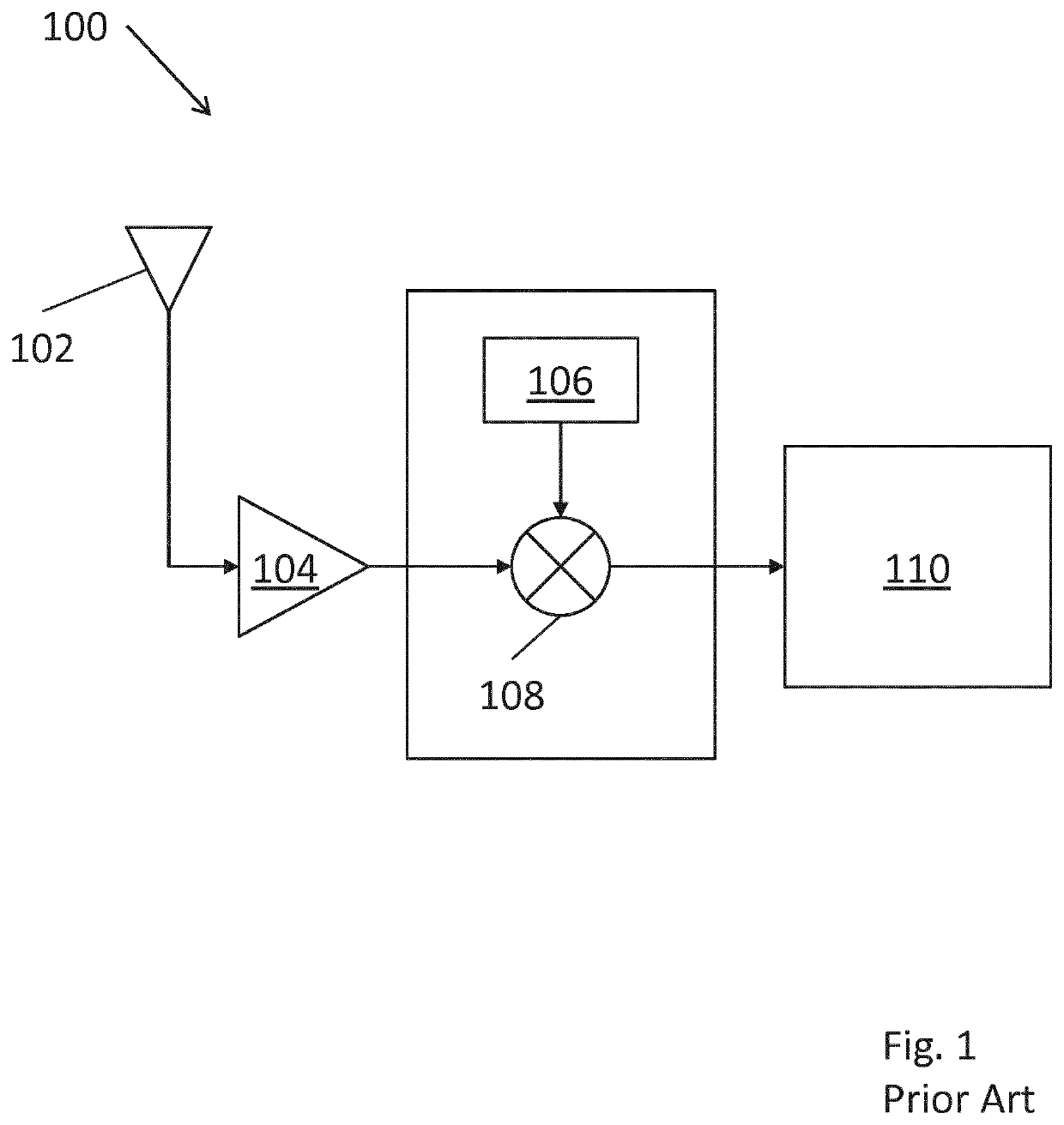
[0065]FIG. 1 is a block diagram of a typical LTE eMTC receiver 100, known in the art per se. The receiver 100 comprises: an antenna 102; a low-noise amplifier (LNA) 104; a frequency synthesiser 106; a mixer 108; and a demodulation module 110. Those skilled in the art will appreciate that this is a highly simplified overview of a practical system, which would typically contain many subsystems.

[0066]Signals received via the antenna 102 are passed through the LNA 104 which amplifies the signals before inputting them to the mixer 108. The mixer 108 also takes as an input a signal produced by the frequency synthesiser 106 in order to down-mix the received signals from the transmission frequency to baseband frequency suited to further processing by the demodulation module 110.

[0067]In order to change between different radio channels, for example during a frequency hopping process, the frequency synthesiser 106 can be tuned to change the frequency of the signal it produces that is input to...


PUM


Abstract

A method of operating a radio receiver arranged to receive a plurality of data symbols transmitted on one of a predetermined set of frequencies. The method comprises receiving a first set of data symbols at a first transmission frequency. The first set of data symbols comprises a message indicating a first frequency sub-set. A synthesiser is calibrated for the one or more frequencies in the first frequency sub-set. A second set of data symbols transmitted on at least one of said one or more frequencies from the first sub-set is received. It is determined from the second set of data symbols whether a network quality metric exceeds a threshold. The synthesiser is calibrated for one or more frequencies in a second frequency sub-set when the network quality metric exceeds the threshold. The second sub-set comprises frequencies that are not in the first sub-set.

Description

CROSS REFERENCE TO RELATED APPLICATIONS[0001]This is the U.S. National Stage of International Application No. PCT / EP2019 / 066389, filed Jun. 20, 2019, which was published in English under PCT Article 21(2), which in turn claims the benefit of Great Britain Application No. 1810760.7, filed Jun. 29, 2018.TECHNICAL FIELD[0002]The present invention relates to improving the efficiency at which a radio receiver can carry out a calibration procedure, particularly although not exclusively, in cellular-based systems such as Long Term Evolution (LTE) systems suited for Internet of Things applications.BACKGROUND[0003]Throughout the course of recent years, the extent and technical capabilities of cellular-based radio communication systems have expanded dramatically. More recently, the Long Term Evolution (LTE) network, a fourth generation (or “4G”) network standard specified by the 3rd Generation Partnership Project (3GPP), has gained popularity due to its relatively high uplink and downlink spe...

Claims


Application Information

Patent Timeline
Patent Type & Authority Patents(United States)
IPC IPC(8): H04W72/04H04B1/7136H04L5/00H04L7/033
CPCH04W72/0453H04B1/7136H04L5/0012H04L7/0331H04B2001/71365H04J11/0073H04J11/0076H04J2013/0096H04W4/70H04L67/12
Inventor ÖSTMAN, KJELLSALMI, MIKAKANGASSUO, TOMMI
Owner NORDIC SEMICONDUCTOR
Why Eureka
Try Eureka