Micromechanical pressure sensor device and corresponding manufacturing method

a pressure sensor and micro-mechanical technology, applied in the direction of fluid pressure measurement, fluid pressure measurement by electric/magnetic elements, instruments, etc., can solve the problems of affecting the performance of the pressure sensor device, unable to contain bubbles in the gel,

Active Publication Date: 2022-09-13
ROBERT BOSCH GMBH
View PDF17 Cites 0 Cited by
  • Summary
  • Abstract
  • Description
  • Claims
  • Application Information

AI Technical Summary

Benefits of technology

[0012]In accordance with the present invention, a separate channel is provided in the periphery of the pressure sensor unit, which preferably has a larger diameter than the access openings above the pressure sensor device and the laterally surrounding stress relief trenches. A bubble-free filling of the pressure sensor unit using a passivation medium, for example, a gel or its uncured precursor, via the channel is thus greatly simplified.
[0019]According to a further preferred refinement of the present invention, the pressure sensor unit is suspended via strip conductors in the sensor substrate. A particularly effective mechanical decoupling of the pressure sensor unit may thus be achieved. The strip conductors may be mechanically stabilized by webs of the substrate material, for example, silicon.

Problems solved by technology

However, bubbles may not be contained in the gel, since this worsens the performance of the pressure sensor device.

Method used


Image

  • Micromechanical pressure sensor device and corresponding manufacturing method
  • Micromechanical pressure sensor device and corresponding manufacturing method
  • Micromechanical pressure sensor device and corresponding manufacturing method

Examples


Embodiment Construction

[0024]In the figures, identical reference signs identify identical or functionally identical elements.

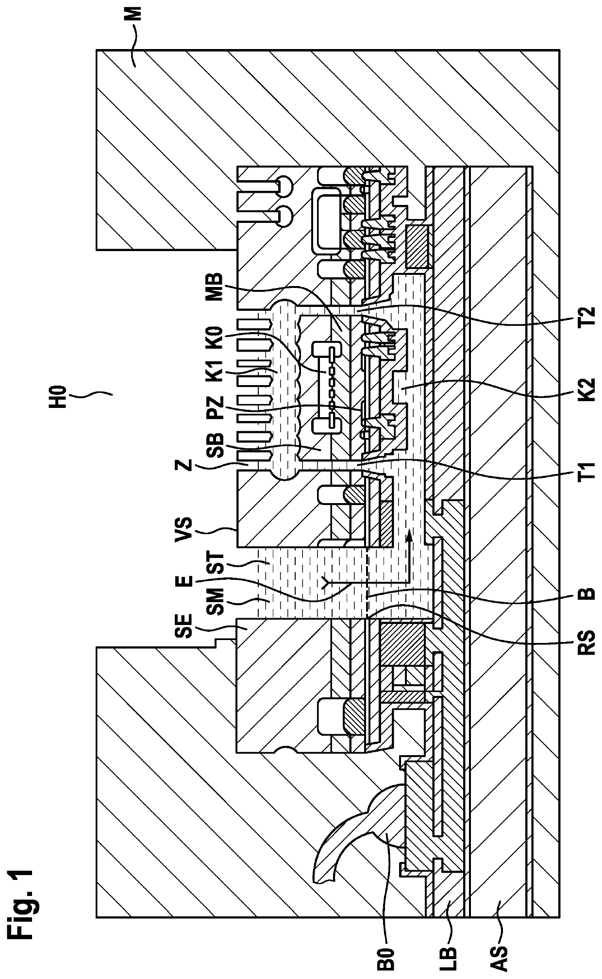
[0025]FIG. 1 shows a schematic cross-sectional view of a micromechanical pressure sensor device according to a first specific embodiment of the present invention.

[0026]In FIG. 1, reference sign SE identifies a sensor substrate having a front side VS and a rear side RS. A pressure sensor unit SB is suspended in the substrate. The suspension is implemented in the present specific embodiment via strip conductors (not shown) in sensor substrate SE, but may optionally or alternatively be implemented by webs of the substrate material, for example, silicon.

[0027]A first cavity K1 is provided above pressure sensor unit SB in sensor substrate SE, which is exposed via a plurality of access openings Z toward front side VS.

[0028]Pressure sensor unit SB suspended in sensor substrate SE is enclosed by a plurality of stress relief trenches T1, T2, which laterally decouple pressure sensor unit SB f...


PUM

PropertyMeasurementUnit
stressaaaaaaaaaa
pressureaaaaaaaaaa
mechanical stressaaaaaaaaaa

Abstract

A micromechanical pressure sensor device is equipped with a sensor substrate including a front side and a rear side. The device includes a pressure sensor unit suspended in the sensor substrate, a first cavity above the pressure sensor unit, which is exposed toward the front side via one or multiple access openings, one or multiple stress relief trenches, which laterally enclose the pressure sensor unit and form a fluidic connection from the rear side to the first cavity, and a circuit substrate, on which the rear side of the sensor substrate is bonded. A second cavity, which is in fluidic connection with the stress relief trenches, is formed below the pressure sensor unit in the circuit substrate. At least one channel is provided in a periphery of the pressure sensor unit, which is in fluidic connection with the second cavity and is exposed to the outside.

Description

FIELD[0001]The present invention relates to a micromechanical pressure sensor device and a corresponding manufacturing method.[0002]Although applicable to arbitrary micromechanical pressure sensor devices, the present invention and its underlying problem will be explained with reference to micromechanical pressure sensor devices based on silicon.BACKGROUND INFORMATION[0003]German Patent Application No. DE 10 2014 200 512 A1 describes a micromechanical pressure sensor device and a corresponding manufacturing method. The micromechanical pressure sensor device includes an ASIC wafer, on whose front side a rewiring unit including a plurality of stacked strip conductor levels and insulation layers is provided. Furthermore, it includes a MEMS wafer, in which a pressure sensor unit is provided, to which pressure is applicable from the front side via multiple through openings. The pressure detection takes place via a deflection of a diaphragm-like first electrode in relation to a second fix...

Claims


Application Information

Patent Timeline
Patent Type & Authority Patents(United States)
IPC IPC(8): G01L19/14B81B7/00G01L9/00G01L19/06G01L19/00
CPCG01L19/146B81B7/0048B81B2201/0264G01L9/0045G01L9/008G01L19/0038G01L19/0627
Inventor SENZ, VOLKMARDANNENBERG, ARNEFRANZ, JOCHEN
Owner ROBERT BOSCH GMBH
Why Eureka
Try Eureka