
Power unit made up of a weld-free assembly of a plurality of battery cells

a technology of battery cells and power units, which is applied in the direction of batteries, cell components, electrical apparatus, etc., can solve the problems of low unit energy content, large and costly assemblies, and large production costs, and achieves the effect of reducing production costs, time-consuming and costly assembly, and reducing production costs

Active Publication Date: 2022-09-06
PYMCO TECH
View PDF11 Cites 0 Cited by
  • Summary
  • Abstract
  • Description
  • Claims
  • Application Information

AI Technical Summary

Benefits of technology

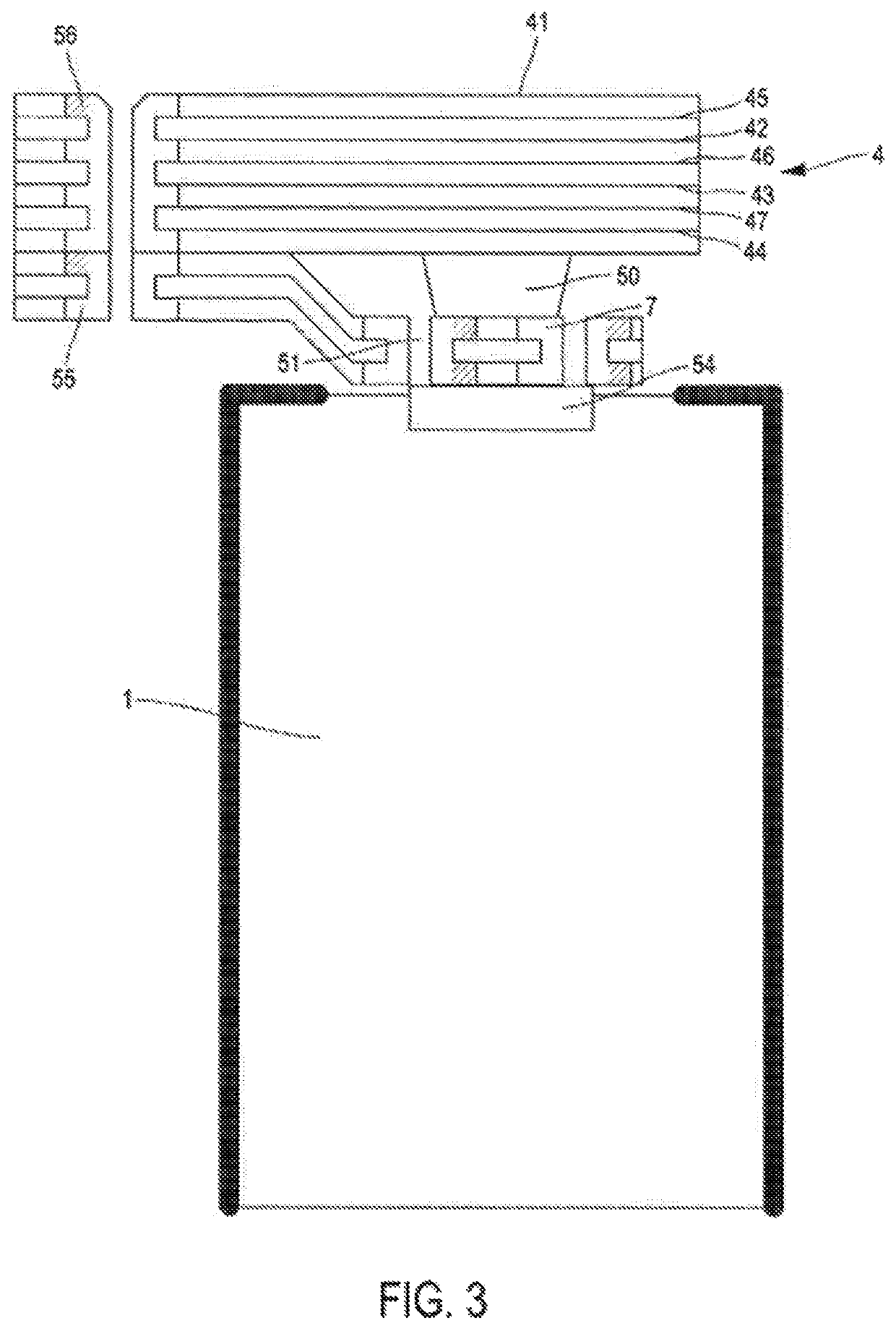
[0045]This solution allows the use of printed circuits as the plate and also allows direct integration of battery control components such as a BMS (battery management system), an electronic circuit controlling module functions, or solid-state contactors using transistors.
[0048]From a thermal point of view, the presence of conductive plates in strong contact with the cells allows optimal thermal management both in cooling and heating, thus allowing improved performance and longer cell life.
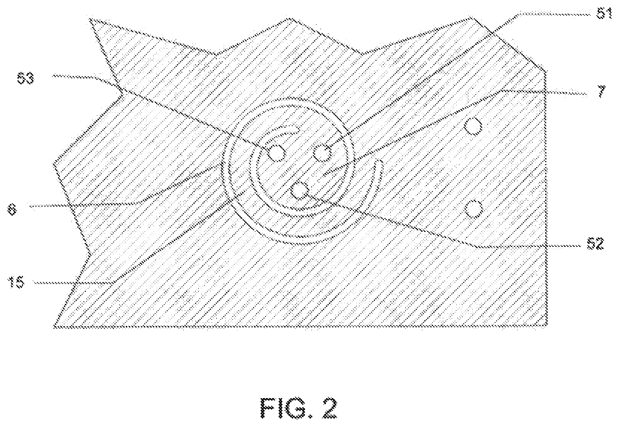
[0050]The technical effect is an improved electrical connection due to the displacement of the contact surface in a plane perpendicular to the axis, which makes it possible to maintain parallelism between the surface forming the positive pole, for example, and the connection element of the unit. Furthermore, this spiral-shaped configuration, whether or not accompanied by a resilient element, makes it possible to ensure a mechanical bearing force greater than that obtained with a deformable blade with respect to a linear hinge zone.

Problems solved by technology

However, their low unit energy content requires large and costly assemblies.
In addition, these assemblies are often the source of performance limitations due to their non-ideal electrical and thermal contact.
The production of such batteries requires tedious, time-consuming and costly assembly.
Furthermore, they do not allow the replacement of one or more cells that might prove to be defective, by after-sales or maintenance services.
This solution is not satisfactory for a high-power unit because batteries made up of a large number of cells (for example, in the order of a hundred cells) assembled in parallel generate very high electric currents to be transported by the interconnection circuits (up to 100 amps or even several hundred amps), which is not possible with the flexible circuits described.
In addition, the material from which the flexible circuits are made (polyamide or polyester film) is very fragile and can be damaged by the friction of the support springs in the event of slight movements, which would result in a loss of electrical contact.
Finally, the springs described in this document do not have sufficient travel and bearing force to ensure effective contact of the flexible contact strip on the cell terminals.the cost of the flexible circuit is directly related to the surface area of same; it is conceivable that it would be very high if the technology proposed in this document were applied to the production of batteries made up of a large number of cells to be connected (very large surface area to be covered);according to this document, the battery can no longer be dismantled after the cover has been closed by a sealing process.
The disadvantage of this type of connection is that it requires cells suitable for welding and costly, bulky, and difficult-to-handle specialized tools to make the multiple solders.
Another major disadvantage of this connection method is that the battery cannot be disassembled, for example, to replace one or more defective cells.
Such resilient plates do not make it possible to guarantee the continuity of electrical contact between the small connection plates and the cells, particularly in the event of weld breaks.
The solutions of the prior art are not entirely satisfactory because the electrical connection between the negative pole is made by pressing on a non-planar conductive surface, which can cause bad contacts, especially when the surface is not degreased or has deposits of dirt with poor conductivity, when the battery contacts are not perfectly conjugated with the flat conductive surfaces of the module.
This solution is not satisfactory either, as contact is only perfect when the surface of the blade is strictly adjacent to the surface of the negative pole, which only occasionally occurs with a resilient hinged blade.

Method used


Image

  • Power unit made up of a weld-free assembly of a plurality of battery cells
  • Power unit made up of a weld-free assembly of a plurality of battery cells
  • Power unit made up of a weld-free assembly of a plurality of battery cells

Examples


Embodiment Construction

[0069]General description of the power unit

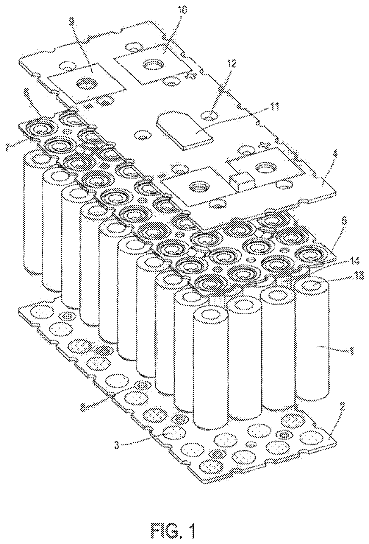
[0070]The power unit shown in FIG. 1 and FIG. 4 includes:[0071]a set of battery cells (1) all oriented parallel to each other and in the same direction, with the metal cap forming the positive pole facing upwards and aligned to form a matrix of N rows and M columns;[0072]a bottom printed circuit (2), the top conductive surface (3) of which ensures the connection with the bottom metal cap constituting the negative pole of the batteries;[0073]a top printed circuit (4), the bottom surface of which ensures the connection, via an intermediate element (5), with the top metal cap constituting the positive pole of the batteries;[0074]an intermediate element (5) having cutouts (6) defining contact surfaces (7) ensuring the electrical and mechanical connection with the cap of the corresponding cell (1).

[0075]Detailed description of the bottom printed circuit (2)

[0076]The bottom printed circuit (2) has a number of functions:

[0077]A—it ensures the mech...


PUM

PropertyMeasurementUnit
diameteraaaaaaaaaa
lengthaaaaaaaaaa
lengthaaaaaaaaaa

Abstract

A power unit made up of a weld-free assembly of a plurality of battery cells having positive and negative contact surfaces, respectively, on the two opposing front ends thereof, the cells being mechanically juxtaposed and parallel with one another, the unit including: a bottom plate having metal contact zones capable of ensuring electrical and optionally thermal connection with the bottom metal base of a cell; a top plate having metal contact zones for ensuring electrical connection with the top cap of a cell; means for connecting with the top caps of the cells, which are resiliently deformable in an axial direction relative to the orientation of the cells.

Description

CROSS-REFERENCE TO RELATED APPLICATIONS[0001]This application is a national phase entry under 35 U.S.C. § 371 of International Patent Application PCT / FR2018 / 052795, filed Nov. 9, 2018, designating the United States of America and published as International Patent Publication WO 2019 / 097146 A1 on May 23, 2019, which claims the benefit under Article 8 of the Patent Cooperation Treaty to French Patent Application Serial No. 17 / 60750, filed Nov. 15, 2017.TECHNICAL FIELD[0002]The present disclosure relates to the field of power units made up of an assembly of a plurality of battery cells connected to each other weldlessly.BACKGROUND[0003]The cells have, at one of the end faces, a cylindrical protuberance with a flat conductive bottom with a cross-section smaller than the cross-section of the cell, generally corresponding to the positive pole, and, at the opposite end, a flat conductive bottom bounded by the protective casing, the cross-section of which is very slightly smaller than the e...

Claims


Application Information

Patent Timeline
Patent Type & Authority Patents(United States)
IPC IPC(8): H01M50/502H01M50/213H01M50/572H01M50/507H01M50/517H01M50/583
CPCH01M50/502H01M50/213H01M50/572H01M2200/103H01M50/517H01M50/507H01M50/583
Inventor GILTON, PIERRE-YVESNGUYEN, MARC
Owner PYMCO TECH
Learn More