Flow control device

a flow control and flow rate technology, applied in the direction of positive displacement liquid engines, laboratory glassware, catheters, etc., can solve the problems of inability to accurately control the dose within the body, difficulty in controlling low flow rate, and complicated known devices

Active Publication Date: 2022-09-06
KONINKLJIJKE PHILIPS NV
View PDF18 Cites 2 Cited by
  • Summary
  • Abstract
  • Description
  • Claims
  • Application Information

AI Technical Summary

Benefits of technology

[0019]This design provides a laminate structure which is easy to produce and to miniaturize. Actuation of the electroactive material layer causes the orifices to open and close so that a flow control function may be implemented. The laminate structure comprises at least two layers which are bonded together, and they are preferably planar in a non-actuated state. The two layers comprise a bottom layer and a top layer bonded or otherwise coupled together. The device can be made to provide very accurate control of very small amounts of liquid, at low power and low cost and with silent operation. The device can be miniaturized to a desired scale.
[0025]The device may comprise a sealing layer which is provided at least around the internal openings of the orifices. This sealing layer enables the valve closed function to be improved.
[0047]The flow control device performs a sampling function and this may prevent saturation of the fluid sensor.

Problems solved by technology

The known devices are generally complicated and they are not able to provide accurate control of the doses within the body.
There are similar difficulties in controlling low flow rates.
There are also difficulties performing a sampling process within a miniaturized device.

Method used


Image

  • Flow control device
  • Flow control device
  • Flow control device

Examples


Embodiment Construction

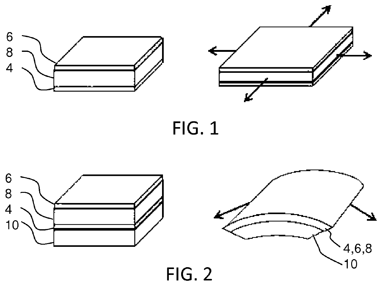
[0064]The invention provides a flow control device comprising a laminate structure of an electroactive material layer and a non-actuatable layer. An array of orifices is formed in one of the layers wherein the orifices are open in one of the rest state and actuated state and the orifices are closed in the other of the rest state and actuated state. Actuation of the electroactive material layer causes orifices to open and close so that flow control function may be implemented.

[0065]The invention makes use of a control device using an electroactive material (EAM). This is a class of materials within the field of electrically responsive materials. When implemented in an actuation device, subjecting an EAM to an electrical drive signal can make them change in size and / or shape. This effect can be used for actuation and sensing purposes.

[0066]There exist inorganic and organic EAMs.

[0067]A special kind of organic EAMs are electroactive polymers (EAPs). Electroactive polymers (EAP) are an ...


PUM


Abstract

A flow control device comprises a laminate structure of an electroactive material layer and a non-actuatable layer. An array of orifices is formed in one of the layers wherein the orifices are open in one of the rest state and actuated state and the orifices are closed in the other of the rest state and actuated state. Actuation of the electroactive material layer causes orifices to open and close so that flow control function may be implemented.

Description

CROSS-REFERENCE TO PRIOR APPLICATIONS[0001]This application is the U.S. National Phase application under 35 U.S.C. §371 of International Application No. PCT / EP2017 / 082195, filed on Dec. 11, 2017, which claims the benefit of EP Patent Application No. EP 16203587.7, filed on Dec. 13, 2016. These applications are hereby incorporated by reference herein. FIELD OF THE INVENTION[0002]This invention relates to a fluid control device, in particular for transport of small doses of fluid.BACKGROUND OF THE INVENTION[0003]Accurate small dose control is critical in many areas such as medicine and fluid and gas delivery.[0004]In healthcare, there is a trend towards the development of so-called Point Of Care (POC) devices, which are small devices, often with disposable components such as cartridges, that can be used in diagnosis and treatment of patients as an alternative to large and expensive analysis equipment.[0005]Such devices may be used to perform diagnostic tests for example to measure the...

Claims


Application Information

Patent Timeline
Patent Type & Authority Patents(United States)
IPC IPC(8): B01L3/00A61M5/142F04B43/04F04B53/10F16K99/00B01F25/31B01F25/316B01F33/30A61M25/00
CPCB01L3/502738A61M5/14276B01F25/311B01F25/316B01F33/30F04B43/043F04B53/1067F16K99/0025F16K99/0049A61M2025/0058B01L2300/0816B01L2300/0867B01L2300/0887B01L2300/12B01L2400/0633B01L2400/082F16K2099/0076F16K2099/0084F16K2099/0088F16K99/0015
Inventor PELSSERS, EDUARD GERARD MARIELIFKA, HERBERTVAN DE MOLENGRAAF, ROLAND ALEXANDERVAN DEN ENDE, DAAN ANTONHAKKENS, FRANCISCUS JOHANNES GERARDUSJOHNSON, MARK THOMASHENDRIKS, CORNELIS PETRUSVAN DE STOLPE, ANJA
Owner KONINKLJIJKE PHILIPS NV
Why Eureka
Try Eureka