
Overload current detection in a circuit interrupting device

a circuit interrupting device and overload current technology, applied in the direction of protective switch details, instruments, heat measurement, etc., can solve the problems of high precision, small displacement achieved by warping of bimetallic devices, and difficult to achieve precise temperature, etc., to achieve fast switching response, sharp drop in magnetic permeability, and precise temperature

Active Publication Date: 2022-08-23
SIEMENS IND INC
View PDF12 Cites 0 Cited by
  • Summary
  • Abstract
  • Description
  • Claims
  • Application Information

AI Technical Summary

Benefits of technology

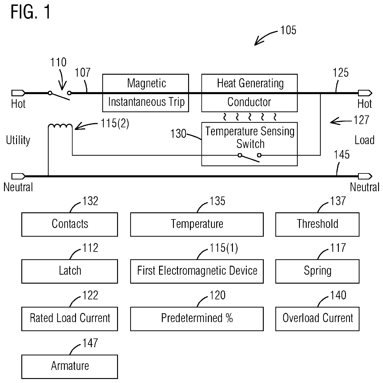
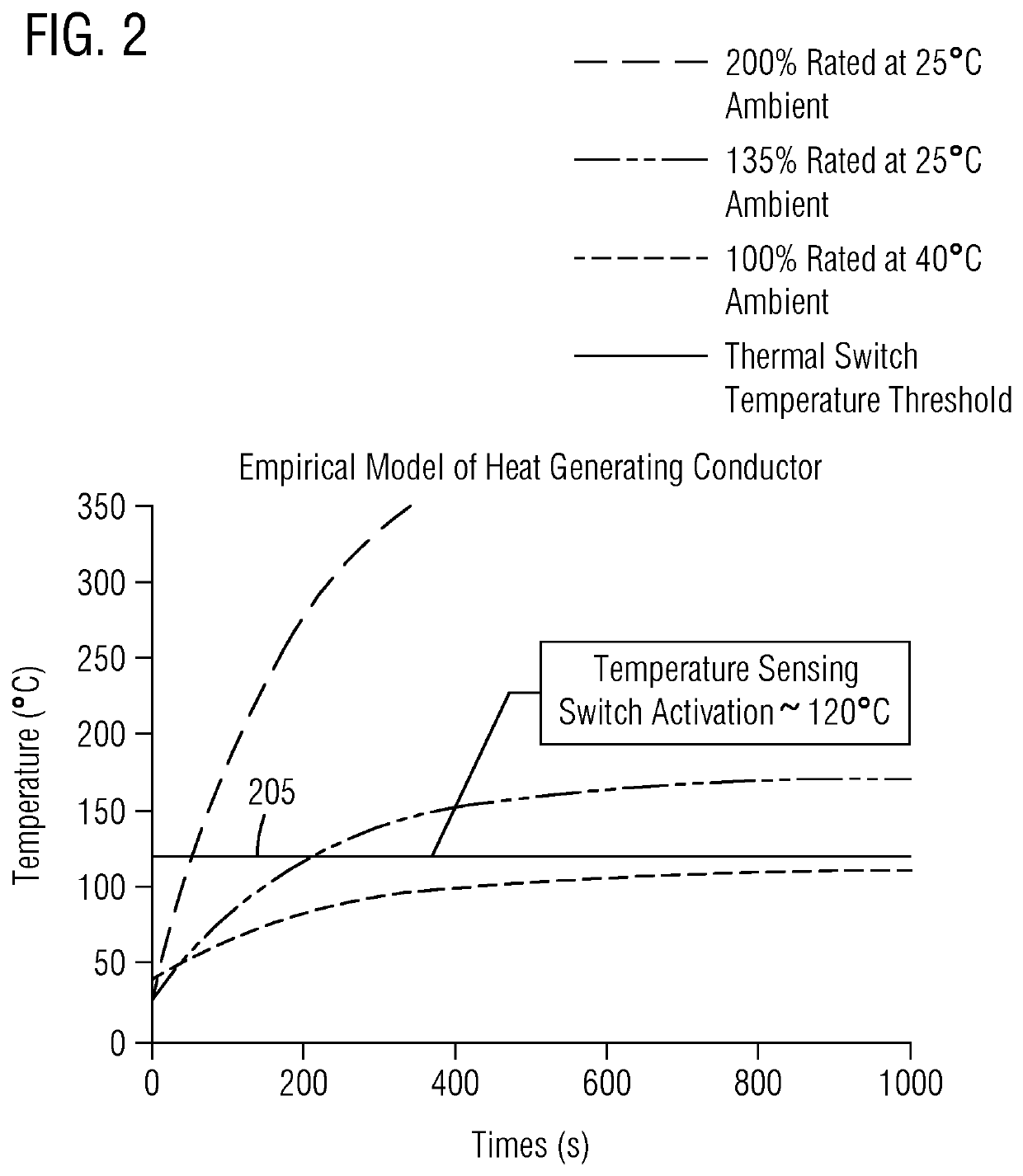
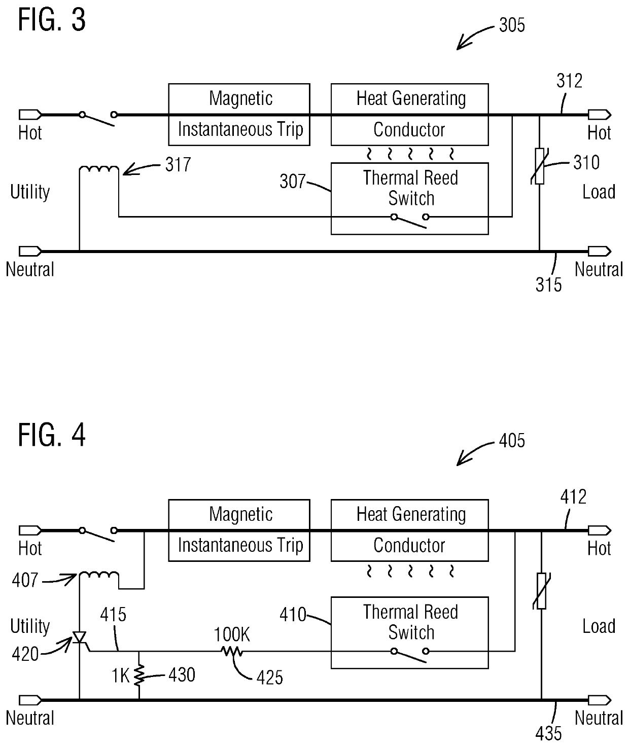
[0007]Briefly described, aspects of the present invention relate to overload current detection in a circuit interrupting device. This invention solves the problem by providing an alternative method and apparatus to the bimetallic device that monitors the temperature of a section of a conductor internal to a circuit breaker and generates a force to unlatch a latch releasing a spring to open a contactor switch removing power from the electrical circuit, and does so at a more precise temperature that is repeatable from unit to unit in mass production. The invention utilizes a new soft magnetic material called Thermorite® developed by Kemet. The magnetic permeability versus temperature characteristic of Thermorite® exhibits a very sharp drop in magnetic permeability at its Curie point. Moreover, Kemet has commercially made available a family of Thermal Reed Switches utilizing Thermorite® technology that have fast switching response and are accurate to within ±2.5° C. The advantage of this invention is that calibration of a thermal overload current detection mechanism of circuit breakers is not necessary. The highly inefficient and costly iterative process of calibrating a bimetallic overload current detection mechanism is eliminated, along with wasted material that is scrapped due to reworking circuit breakers that nonconformed, thus saving precious time and money during mass production of circuit breakers. The cost savings, improvement in test process, efficiency, and factory line throughput more than offset the cost of adding a Thermal Reed Switch and a second electromagnet. In the case of an electronic circuit breaker for ground fault detection and / or arc fault detection, the second electromagnet already exists as a trip mechanism that is activated upon detection of a fault. So, the only additional cost is the Thermal Reed Switch.

Problems solved by technology

If the rated current is exceeded, then the conductor will overheat to a point that the insulation melts resulting in hazardous conditions of electrical shock due to exposed voltage potential energy and of flame ignition due to exposed heat energy.
The utilization of a bimetallic device presents several problems.
The amount of displacement achieved from warping of the bimetallic device is very small requiring a high degree of precision.
This especially becomes problematic when mass producing circuit breakers that are being sold commercially.
This is a very time consuming, inefficient, costly process that still results in approximately 15 percent nonconforming units.
And test time and cost really add up when mass producing millions of units per year.
There has not been a simple alternative solution that has high accuracy without adding electronic sensors, amplifiers, and potentially a microprocessor for overcurrent-time calculations, and an electronic ac-dc adaptor power supply to provide power to the electronics.
The highly inefficient and costly iterative process of calibrating a bimetallic overload current detection mechanism is eliminated, along with wasted material that is scrapped due to reworking circuit breakers that nonconformed, thus saving precious time and money during mass production of circuit breakers.
So, the only additional cost is the Thermal Reed Switch.

Method used


Image

  • Overload current detection in a circuit interrupting device
  • Overload current detection in a circuit interrupting device
  • Overload current detection in a circuit interrupting device

Examples


Embodiment Construction

[0017]To facilitate an understanding of embodiments, principles, and features of the present invention, they are explained hereinafter with reference to implementation in illustrative embodiments. In particular, they are described in the context of a circuit interrupting device without a bimetallic overload current detection mechanism. A circuit interrupting device comprises a thermal overload current detection mechanism including a temperature sensing switch. For example, a circuit interrupting device includes a Thermal Reed Switch that utilizes a new soft magnetic material called Thermorite®. The Thermal Reed Switch has a fast switching response and is accurate to within ±2.5° C. The highly inefficient and costly iterative process of calibrating a bimetallic overload current detection mechanism is eliminated, along with wasted material. Embodiments of the present invention, however, are not limited to use in the described devices or methods.

[0018]The components and materials descr...


PUM

PropertyMeasurementUnit
temperatureaaaaaaaaaa
temperaturesaaaaaaaaaa
magnetic forceaaaaaaaaaa

Abstract

A circuit interrupting device with overload current detection is provided. It comprises a hot conductor, a main contactor and a first electromagnetic device configured to remove power from an electrical circuit when overload current exceeds a predetermined % of a rated load current. It further comprises a section of conductor that generates heat and a thermal overload current detection mechanism including a temperature sensing switch having contacts. The temperature sensing switch closes the contacts when a temperature reaches a predefined temperature threshold corresponding to an overload current, in which case the temperature sensing switch electrically couples power to a second electromagnet which is disposed across the hot conductor and a connection to a neutral conductor. The energized second electromagnet generates a magnetic force capable of moving an armature that unlatches the latch releasing the spring to open the main contactor removing power from the electrical circuit.

Description

BACKGROUND1. Field[0001]Aspects of the present invention generally relate to overload current detection in a circuit interrupting device.2. Description of the Related Art[0002]Electrical power is distributed to loads throughout buildings using insulated conductors of different sizes appropriate for the amplitude of current being delivered to the load. The amount of current for continuous safe operation for a particular wire gage size is known as a rated current. If the rated current is exceeded, then the conductor will overheat to a point that the insulation melts resulting in hazardous conditions of electrical shock due to exposed voltage potential energy and of flame ignition due to exposed heat energy. Initially fuses were implemented to prevent these hazardous conditions resulting from overloading the electrical circuit. Fuses were eventually replaced by circuit breakers which function as resettable switches. The circuit breaker typically has a robust main contactor that is spri...

Claims


Application Information

Patent Timeline
Patent Type & Authority Patents(United States)
IPC IPC(8): H02H5/00G01R31/52G01K7/38G01R31/12H02H1/00H02H3/10H02H5/04
CPCG01R31/52G01K7/38G01R31/1272H02H1/0007H02H3/105H02H5/048H01H71/142H01H71/402
Inventor KINSEL, HUGH T.ENDOZO, JOSELITO
Owner SIEMENS IND INC
Learn More