
Mirrors to extend sensor field of view in self-driving vehicles

a self-driving vehicle and sensor field technology, applied in the direction of process and machine control, using reradiation, instruments, etc., can solve the problems of increasing system cost and processing complexity, obstructing the fov of sensors by the trailer of a cargo truck, and affecting the operation of large-sized vehicles such as cargo vehicles

Active Publication Date: 2022-07-19
WAYMO LLC
View PDF16 Cites 0 Cited by
  • Summary
  • Abstract
  • Description
  • Claims
  • Application Information

AI Technical Summary

Benefits of technology

This solution enhances the sensor's field of view, reducing blind spots and improving the vehicle's ability to detect objects in obstructed areas, thereby enhancing safety and operational efficiency in autonomous driving modes without increasing system costs or complexity.

Problems solved by technology

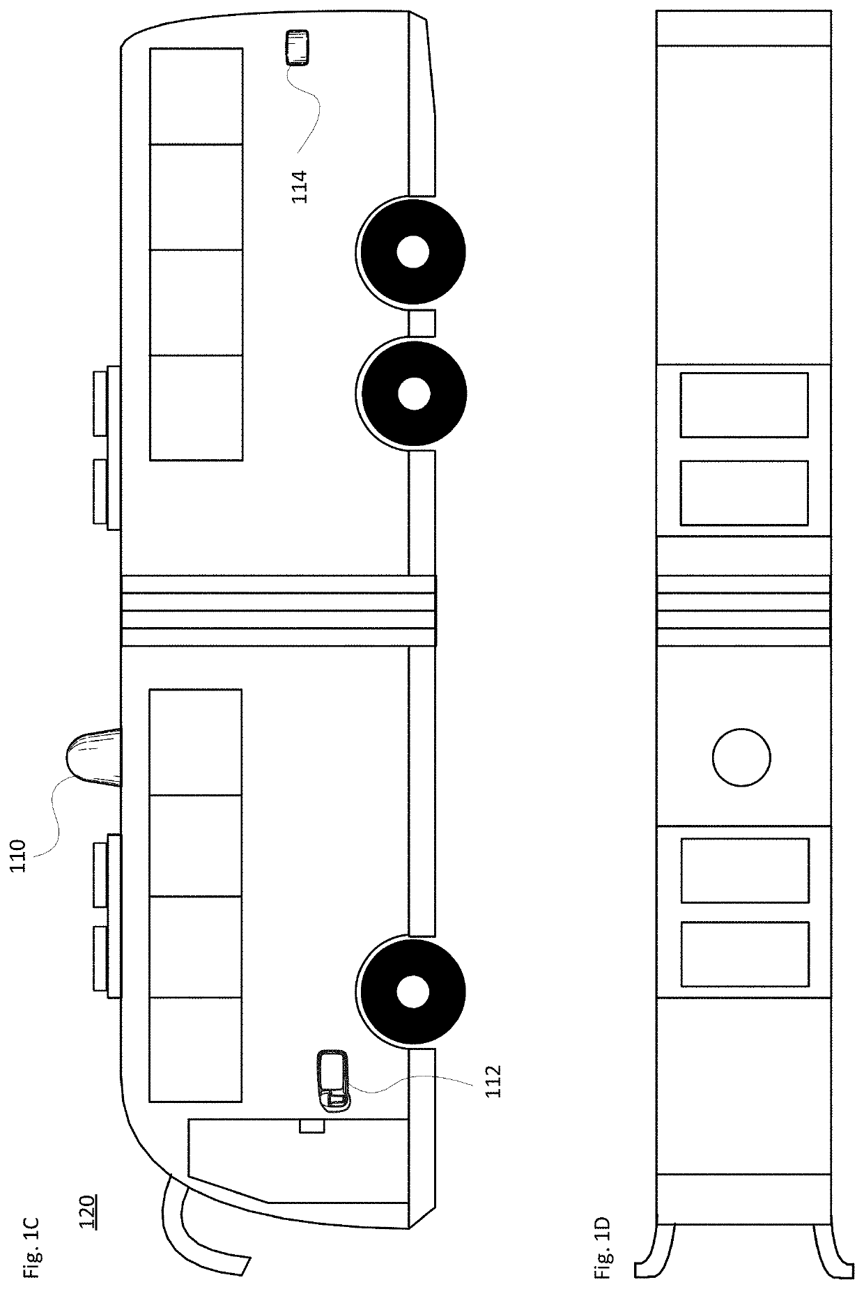
Large-sized vehicles such as cargo vehicles, buses and construction equipment can encounter particular challenges compared to smaller passenger vehicles such as sedans or vans.
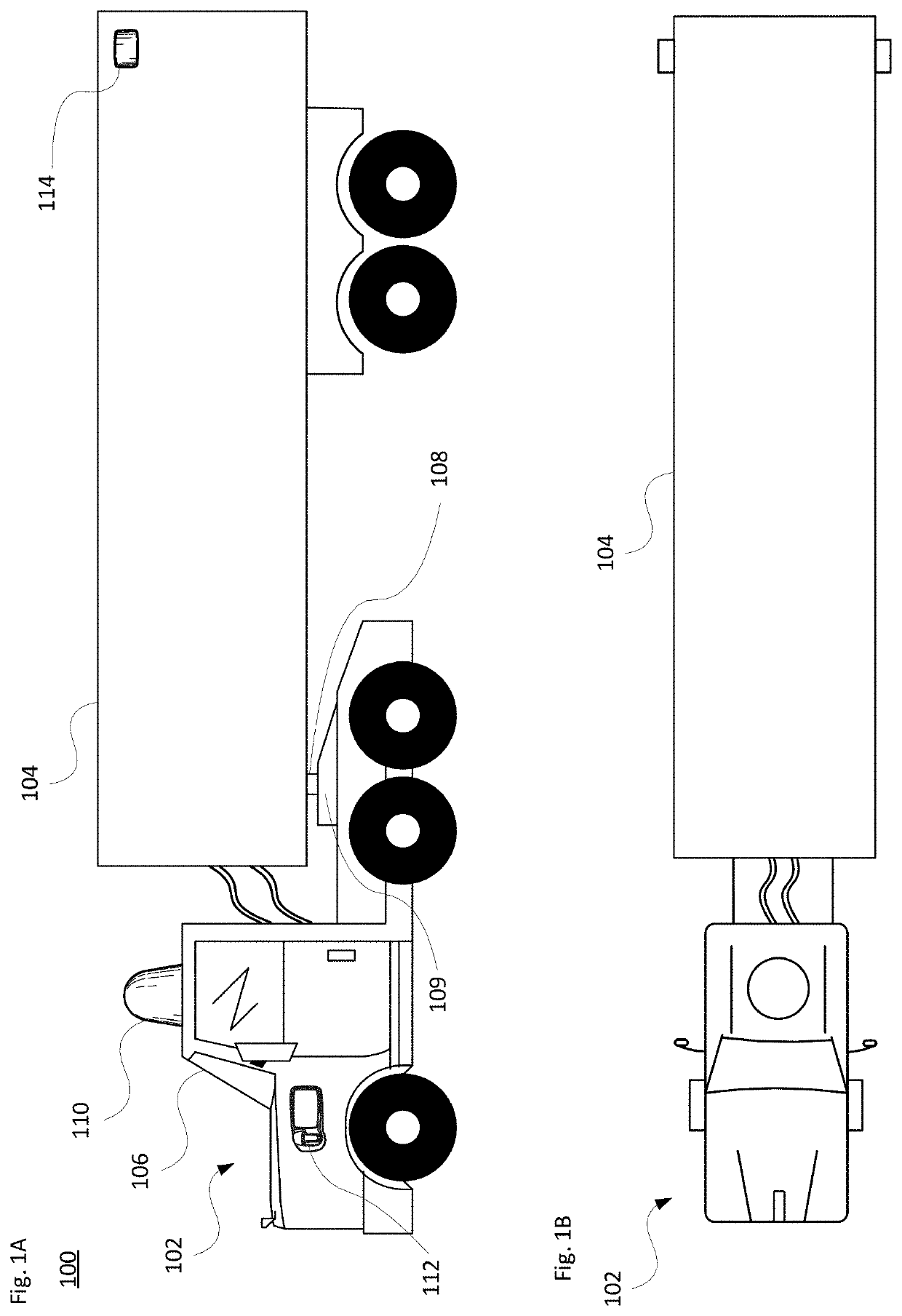
For instance, the trailer of a cargo truck may obstruct the FOV of sensors mounted on the truck's tractor, especially during a turning maneuver.
However, adding sensors can increase system cost as well as processing complexity, for example from a sensor fusion perspective.
Regardless of the number or type of added sensors, some areas around the vehicle may be obscured or have reduced visibility due to physical limitations on where the sensors can be placed.
Such mirrors can reflect or redirect beams that would otherwise be wasted.
Some beams may be wasted due to obstruction by the trailer.
Other beams may be wasted because they are emitted at high pitch angles to the side.

Method used


Image

  • Mirrors to extend sensor field of view in self-driving vehicles
  • Mirrors to extend sensor field of view in self-driving vehicles
  • Mirrors to extend sensor field of view in self-driving vehicles

Examples


example implementations

[0058]In view of the structures and configurations described above and illustrated in the figures, various implementations will now be described.

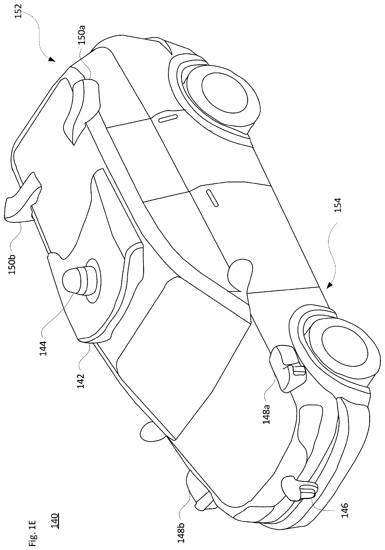
[0059]Information obtained from one or more sensors is employed so that the vehicle may operate in an autonomous mode. Each sensor, or type of sensor, may have a different range, resolution and / or field of view (FOV).

[0060]For instance, the sensors may include a long range, narrow FOV lidar and a short range, tall FOV lidar. In one example, the long range lidar may have a range exceeding 50-250 meters, while the short range lidar has a range no greater than 1-50 meters. Alternatively, the short range lidar may generally cover up to 10-15 meters from the vehicle while the long range lidar may cover a range exceeding 100 meters. In another example, the long range is between 10-200 meters, while the short range has a range of 0-20 meters. In a further example, the long range exceeds 80 meters while the short range is below 50 meters. Intermedi...


PUM


Abstract

The technology relates to enhancing or extending the field of view of sensors for vehicles configured to operate in an autonomous driving mode. One or more mirrors are used to reflect or redirect beams emitted from onboard sensors that would otherwise be wasted, for instance due to obstruction by a portion of the vehicle or because they are emitted at high pitch angles to the side. The mirrors are also used to redirect incoming beams from the external environment toward one or more of the onboard sensors. Using mirrors for such redirection can reduce or eliminate blind spots around the vehicle. A calibration system may be employed to account for mirror movement due to vibration or wind drag. Each mirror may be a front surface mirror. The mirrors may be positioned on the vehicle body, on a faring, or extending from a sensor housing on the vehicle.

Description

BACKGROUND[0001]Autonomous vehicles, such as vehicles that do not require a human driver, can be used to aid in the transport of trailered (e.g., towed) cargo, such as freight, livestock or other items from one location to another. Other types of articulated vehicles may also transport cargo or passengers. Such vehicles may operate in a fully autonomous mode without any in-vehicle passenger input or a partially autonomous mode where a person may provide some driving input. One or more sensors can be used to detect nearby objects in the environment, and the vehicle may use information from the sensors when driving in an autonomous mode. Depending on the size, shape and orientation of the vehicle, there may be one or more blind spots around the vehicle. Blind spots may be reduced by adding more sensors. However, each added sensor results in increased cost and may increase computer processing power requirements. Also, this approach may not be physically feasible in certain instances.BR...

Claims


Application Information

Patent Timeline
Patent Type & Authority Patents(United States)
IPC IPC(8): G01S7/48G01S7/481G05D1/02G01S7/03B60W10/04B60W10/20B60W10/18B60W30/18B60R1/06B60R1/12G05D1/00
CPCG01S7/4811B60R1/06B60R1/12B60W10/04B60W10/18B60W10/20B60W30/18G01S7/03G05D1/0088G05D1/024G05D1/0242G05D1/0246G05D1/0257B60R2001/1284B60W2300/126B60W2400/00B60W2420/52B60W2710/18B60W2710/20B60W2720/106G05D2201/0213B60R11/00B60R16/0231B60R2011/004B60R2001/1223B60R2300/802B60R11/04G01S2013/93273G01S2013/9323G01S13/931G01S2013/9315G01S13/867G01S13/865G01S13/862G01S17/931G01S17/87G01S17/86B60W2710/08B60W2300/147B60W2420/408
Inventor CHEN, MINGCHENGPITZER, BENJAMINDROZ, PIERRE-YVESGROSSMAN, WILLIAM
Owner WAYMO LLC
Learn More