Tube and chamber type heat exchange apparatus having an enhanced medium directing assembly

a heat exchange apparatus and chamber-type technology, applied in the field of heat exchangers, can solve the problems of design methodology, higher pressure drop, and higher pressure drop

Active Publication Date: 2022-07-19
MIKUTAY CORP
View PDF13 Cites 0 Cited by
  • Summary
  • Abstract
  • Description
  • Claims
  • Application Information

AI Technical Summary

Benefits of technology

[0013]The present invention is an enhanced tube and chamber type heat exchanger, for use in a heat exchanger application where it is desired to transfer heat from a first heat exchange medium to a second heat exchange medium. The heat exchanger is provided with a chamber assembly, the chamber assembly generally taking a form of a longitudinally extended hollow chamber. In an embodiment of the present invention, the chamber assembly may be formed in a rectangular parallelepiped configuration. The chamber assembly is further provided with a chamber inlet and a chamber outlet, as means to facilitate the flow of the first heat exchange medium into the chamber assembly, and then to discharge the first heat exchange medium out of the chamber assembly, respectively. The chamber inlet is generally located on a first longitudinal end of the chamber assembly, while the chamber outlet is generally located on a second longitudinal end of the chamber assembly. In a typical heat exchanger application, the first heat exchange medium is guided to flow inside the chamber assembly, while the second heat exchange medium is directed to flow around the exterior surface of the chamber assembly, with the material comprising the chamber assembly acting as a primary surface to facilitate the flow of heat between the first heat exchange medium and the second heat exchange medium. Heat may travel into the heat exchanger or out of the heat exchanger, dependent upon the nature of the application of the heat exchanger.
[0014]Disposed within the chamber assembly is a medium directing assembly. The medium directing assembly is provided as a means to facilitate desired flow arrangement of the first heat exchange medium directed into the chamber assembly, generally with a desire to improve convective heat transfer effect of the first heat exchange medium by energizing the first heat exchange medium by introducing mixing and eddying effect to the flow, improvement of which is known in the art to generally increase the performance of the overall heat exchanger. The medium directing assembly is also positioned within the chamber assembly to form and locate a plurality of energized first heat exchange medium flow generally adjacent to the interior surface of the chamber body, thereby facilitating greater heat transfer effect by locating the energized flow adjacent to the primary surface that facilitates heat conduction between the first and the second heat exchange medium. The medium directing assembly is further utilized to create and then locate a plurality of flow channels extending generally the longitudinal span of the chamber assembly, locating the flow channels between the chamber assembly and the medium directing assembly, utilizing the plurality of highly energized flow created by the medium directing assembly to facilitate greater heat transfer effect to the first heat exchange medium flowing within the plurality of flow channels without unduly increasing pressure drop effect to the first heat exchange medium.
[0015]As the flow channels are located adjacent to the primary surface provided by the chamber body, a greater heat transfer effect can be achieved. The flow channels are generally free of physical obstruction for the longitudinal span of the respective flow channels, minimizing pressure drop effect to the first heat exchange medium. The medium directing assembly is yet further utilized to form a plurality of serially interconnected longitudinally partitioned sections within the chamber assembly to obtain the desired flow of the first heat exchange medium, to ensure that the entire longitudinal span of the chamber assembly is fully utilized, effectively, for heat transfer purposes, thereby maximizing heat transfer potential of the chamber assembly. Select partitioned sections are further utilized to function like an inlet tube and an outlet tube typically used in a conventional tube and chamber type heat exchanger, without having the need to attach separate physical components to the chamber assembly, minimizing cost.

Problems solved by technology

However, there may be drawbacks to the design methodology, such as higher pressure drop effect as noted earlier.
All these characteristics generally result in higher pressure drop to the first heat exchange medium flow, which is not desirable, as higher pressure drop generally results in reduced performance of the heat exchanger, requiring larger pumping mechanism to facilitate a greater flow of the first heat exchange medium.
Without a larger pumping mechanism, the heat exchanger may need to be enlarged to attain desired performance, which generally results in higher cost as well as a need for a larger packaging space.
The fin members are attached to the exterior surface of the tube members to supplement the tube members in transferring heat between the first heat exchange medium and the second heat exchange medium, due to limited availability of a primary heat transfer surface provided by the tubular members.
Due to the fragility of fin members in general, the occurrence of damage to the fin members is common, generally diminishing the effectiveness of the heat exchanger, or in some instances, resulting in the heat exchanger being inoperable, due to terminally restricted flow of the first heat exchange medium.
Furthermore, higher fin member density generally drastically increases pressure drop of the first heat exchange medium fed through such a contraption, reducing the effectiveness of the heat exchanger as a result.
As the performance of the heat exchanger is negatively affected, the heat exchanger may need to be larger in physical size to achieve the desired performance, which generally results in a need for additional raw material, which in turn results in additional weight and cost, as well as requiring additional packaging space for the heat exchanger placement.
Furthermore, secondary heat transfer surfaces in the form of fin members are generally known in the art as less efficient in transferring heat than the primary surfaces provided by the tube members.
With the tube and fin heat exchanger, due to its design configuration, primary surfaces are generally provided only on a top and a bottom vertical portions of a typical flow path for the first heat exchange medium, provided by tubular members, while the two lateral portions of the flow path for the first heat exchange medium are generally provided by the secondary surfaces in the form of fin members, generally diminishing the performance of the heat exchanger relative to heat exchangers with a higher concentration of primary surface for heat exchange purposes.
If the leading edge is somehow attached or engaged to some other component within the heat exchanger, the desired effect is typically not achieved, thereby diminishing the heat transfer performance of the heat exchanger as a result.
The feature, however, is not desirable as it is prone to deform with the flow, especially with higher velocity flow of the heat exchange medium or when heat is applied.

Method used


Image

  • Tube and chamber type heat exchange apparatus having an enhanced medium directing assembly
  • Tube and chamber type heat exchange apparatus having an enhanced medium directing assembly
  • Tube and chamber type heat exchange apparatus having an enhanced medium directing assembly

Examples


Embodiment Construction

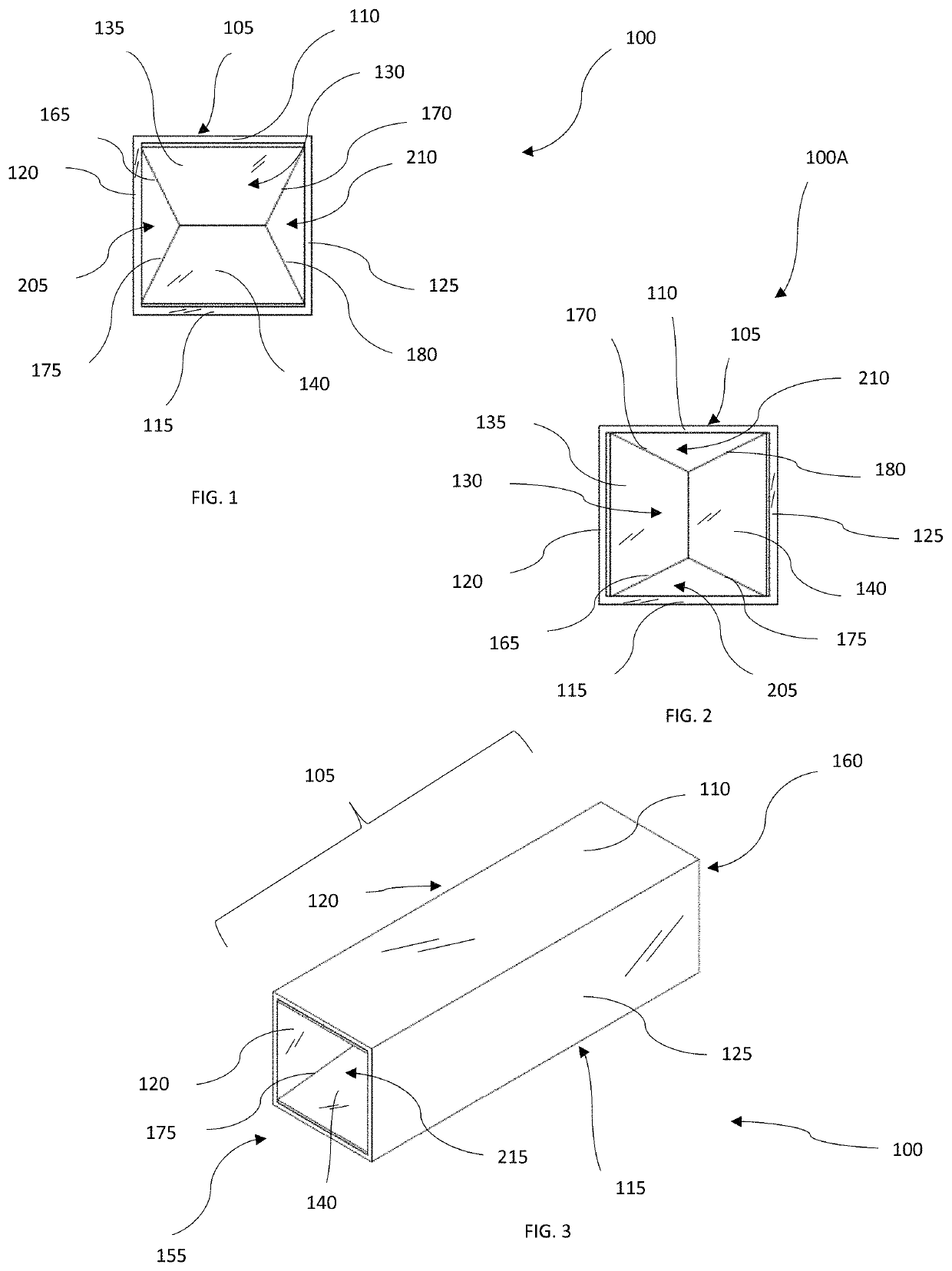
[0060]Referring to the drawings and in particular FIG. 1 and FIG. 3, an embodiment of a heat exchanger 100 is shown. The heat exchanger 100 is generally for use when heat is desired to be transferred from a first heat exchange medium to a second heat exchange medium. Heat may travel into the heat exchanger 100 or out of the heat exchanger 100, dependent upon the nature of the application of the heat exchanger 100. The heat exchanger 100 is provided with a chamber assembly 105, with a chamber inlet 155 located on a first longitudinal end of the chamber assembly 105 and a chamber outlet 160 located on a second longitudinal end of the chamber assembly 105. The chamber assembly 105 is a longitudinally extended body with a hollow interior, permitting the flow of the first heat exchange medium inside the chamber assembly 105. The chamber inlet 155 is an orifice fluidly connected to the hollow interior of the chamber assembly 105, providing means to introduce the first heat exchange medium...


PUM


Abstract

A heat exchanger having a chamber assembly defining a hollow space within, the chamber assembly having an input and a discharge means of a heat exchange medium. Disposed within the chamber assembly is a medium directing assembly. The medium directing assembly defined by a plurality of panel members arranged in a longitudinally extended manner positioned at an acute angle relative to the chamber assembly longitudinal axial characteristics, having an angled lateral edges whereby a first and a second longitudinal ends are provided with wider lateral width, while the medial section of the medium directing assembly is substantially narrower. The medium directed assembly providing a plurality of serially interconnected chambers within the chamber assembly to maximize chamber assembly and heat exchange medium interface, a structured flow path arrangement for the heat exchange medium, as well as means to energize the flow of the heat exchange medium for the desired results.

Description

BACKGROUND OF THE INVENTION[0001]The present invention relates to heat exchangers utilized to transport heat from one heat exchange medium to another, and more specifically related to a tube and chamber type heat exchange apparatus having a medium directing assembly disposed within a chamber assembly, utilizing the medium directing assembly to enhance the flow pattern of a heat exchange medium for the desired effect.DISCUSSION OF THE RELATED ART[0002]In a typical tube and chamber type heat exchanger, a hollow chamber assembly is provided with a medium directing insert disposed within the chamber assembly to facilitate the desired flow of a heat exchange medium within the chamber assembly. Generally, at least two heat exchange mediums are utilized in a tube and chamber type heat exchanger to facilitate heat transfer between the two heat exchange mediums. A first heat exchange medium is typically fed inside the chamber assembly while a second heat exchange medium is directed to flow o...

Claims


Application Information

Patent Timeline
Patent Type & Authority Patents(United States)
IPC IPC(8): F28F1/40F28F9/22F28F1/04
CPCF28F1/40F28F1/04F28F9/22F28F2009/222F28F13/12F28D7/1684
Inventor NITTA, TAKEYOSHI
Owner MIKUTAY CORP
Why Eureka
Try Eureka