Device for the extraction of machining dust

a technology for machining dust and extraction devices, which is applied in the direction of manufacturing tools, chemistry apparatuses and processes, working accessories, etc., can solve the problems of large floor space, unsuitable use of cooling fluids, and inability to extract machining dust,

Active Publication Date: 2022-07-12
NIKKEN KOSAKUSHO EURO
View PDF57 Cites 0 Cited by
  • Summary
  • Abstract
  • Description
  • Claims
  • Application Information

AI Technical Summary

Benefits of technology

[0014]The present invention provides a simplified means for the removal of material waste which does not alter the characteristics of a work piece and / or require a lot of floor space to install.
[0066]Having the nozzle section substantially dome shaped facilitates the funneling of machining dust through the tool holder assembly.

Problems solved by technology

Material waste, for example dust particles, is generated during the machining process which if not removed from the vicinity of the material extraction point can lead to flaws in the finished article and / or damage to the cutting tool.
In some applications, the use of a cooling fluid is undesirable as the cooling fluid would alter the characteristics of the work piece.
However such systems, especially for industrial sized work, require a lot of floor space in addition to the space for the machining equipment.
In addition, such systems are not suitable for the extraction of large fragments of material waste.
For composite machine operations, machining dust is both an irritant raising health and safety issues but also abrasive, causing wear to spindles and guideways.
Additionally it is electrically conductive and has the potential to short out systems.
These issues prevent machining of composites on existing standard equipment, requiring the purchase of bespoke machining platforms having integral extraction and sealed mechanical and electrical systems.
This can be a very expensive purchase especially if a project requiring the machining of composites is a one-off or such projects are few and far between.

Method used


Image

  • Device for the extraction of machining dust
  • Device for the extraction of machining dust
  • Device for the extraction of machining dust

Examples


first embodiment

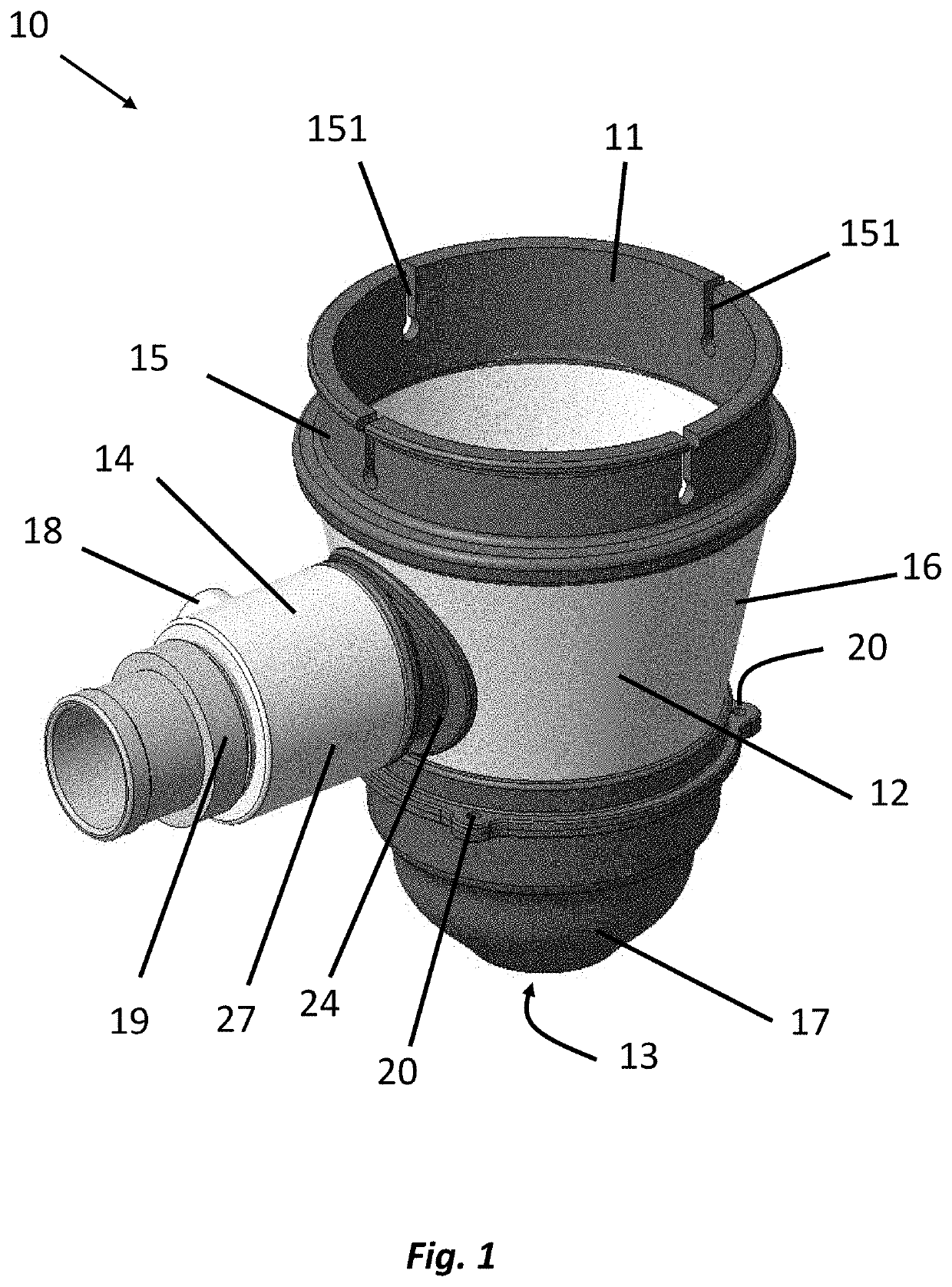
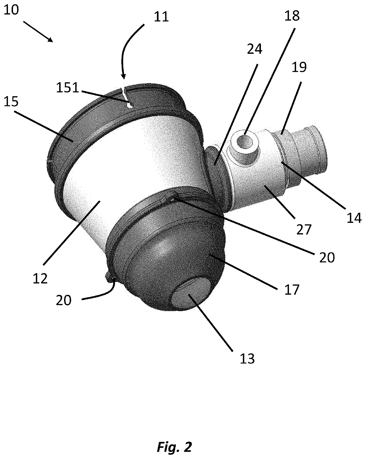
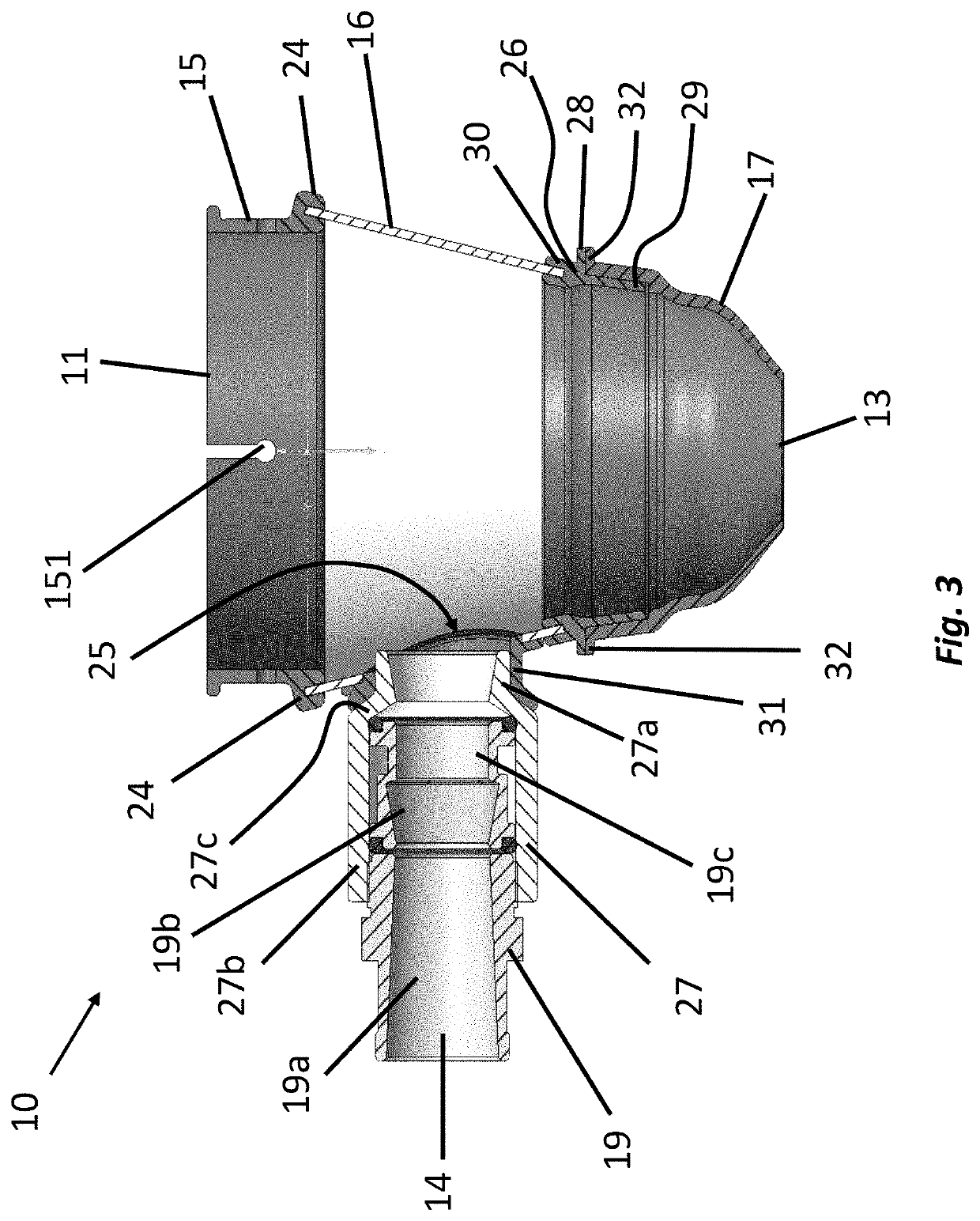
[0082]Referring to FIGS. 1 to 4, a device 10 in accordance with a first aspect of the invention is shown. The device 10 is configured to facilitate the removal of machining dust from the vicinity of the material extraction point during a machining process.

[0083]The device 10 comprises a body 12 and a Venturi mechanism 14.

[0084]The body 10 includes a first opening 11 at a first end thereof and a second opening 13 at a second end thereof. The first end is opposite the second end.

[0085]The first opening 11 is configured to receive a tool holder 23 therethrough (see FIG. 4) and the second opening is configured to receive a cutting tool (not shown) therethrough. The body 10 acts as a cowling for the tool holder 23.

[0086]The body 10 is made up of three sections, a connector portion 15, a central portion 16 and a nozzle portion 17.

[0087]While in the embodiment shown, the connector portion 15, the central portion 16 and the nozzle portion 17 are separate components, it would be understood t...

second embodiment

[0129]Referring to FIG. 5, a device 10a in accordance with the first aspect of the invention is shown.

[0130]The device 10a of the second embodiment is very similar to the first embodiment and the same reference numerals have been used to identify identical features.

[0131]The device 10a of the second embodiment mainly differs from that of the first embodiment in relation to the direction the hose barb 18a extends from the coupling 27a. In one embodiment the hose barb extends outwardly from the left-hand side of the coupling and in the other embodiment, the hose barb extends outwardly from the right-hand side of the coupling.

[0132]The device 10a is shown connected to a waste collection system in the form of a filter bag 12.

[0133]A hose clamp 22 is provided on the connector portion 15 for facilitating the coupling of connector portion 15 to the section of the machining machine. In the embodiment shown, the hose clamp 22 is in the form of a worm drive hose clip, although it would be und...


PUM

PropertyMeasurementUnit
speedaaaaaaaaaa
metallicaaaaaaaaaa
temperatureaaaaaaaaaa

Abstract

The present invention provides a device (10) for the extraction of machining dust. The device (10) comprises a body (12) configured to be coupled to a section of a machining machine. The body (12) having a first opening (11) at a first end thereof and a second opening (13) at a second end thereof. The first end is opposite the second end, and the first opening (11) is configured to receive a tool holder therethrough and the second opening (13) configured to receive a cutting tool therethrough. The device also comprises a Venturi mechanism (14) connected to the body (12) and in fluid communication with said second opening (13). The Venturi mechanism (14) is configured to facilitate the suction of machining dust through the second opening (13) and through the Venturi mechanism (14).

Description

FIELD OF THE INVENTION[0001]The present invention relates to a device for the extraction of machining dust, in particular, for the extraction of composite dust particles. The present invention also relates to a milling machine tool holder assembly.BACKGROUND OF THE INVENTION[0002]A machining process, for example milling, drilling, trimming etc., is usually employed to an article in a number of industries to get the article in a state suitable for its intended use.[0003]Such processes involve controlled material removal by means of a cutting tool. Material waste, for example dust particles, is generated during the machining process which if not removed from the vicinity of the material extraction point can lead to flaws in the finished article and / or damage to the cutting tool.[0004]A known method for the removal of material waste is by means of a cooling fluid which also acts as a medium for regulating the working temperature of the cutting tool. In some applications, the use of a c...

Claims


Application Information

Patent Timeline
Patent Type & Authority Patents(United States)
IPC IPC(8): B23Q11/00
CPCB23Q11/0046B23C2230/08Y10T409/304088B08B15/04B24B55/10B28D7/02
Inventor BROWN, ADAMEASTER-ROBINSON, ROWANRAY, NATHAN
Owner NIKKEN KOSAKUSHO EURO
Why Eureka
Try Eureka