
Region of interest capture for electronic devices

Active Publication Date: 2022-07-05
QUALCOMM INC
View PDF4 Cites 0 Cited by
  • Summary
  • Abstract
  • Description
  • Claims
  • Application Information

AI Technical Summary

Benefits of technology

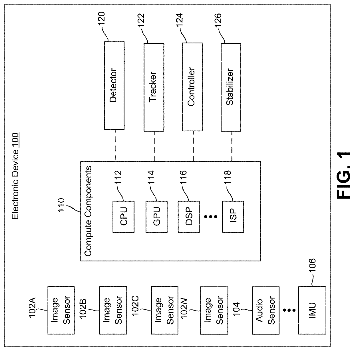
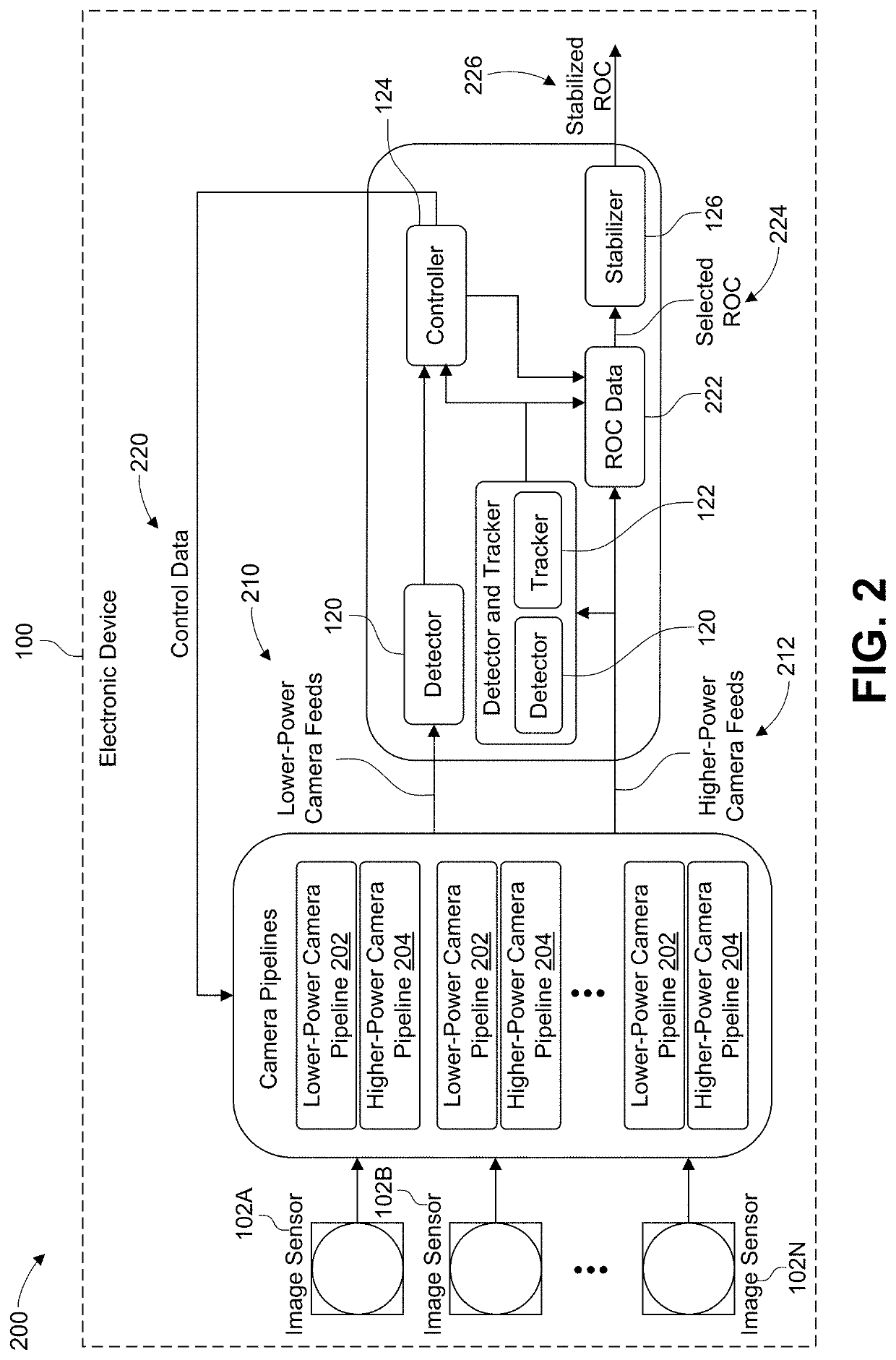
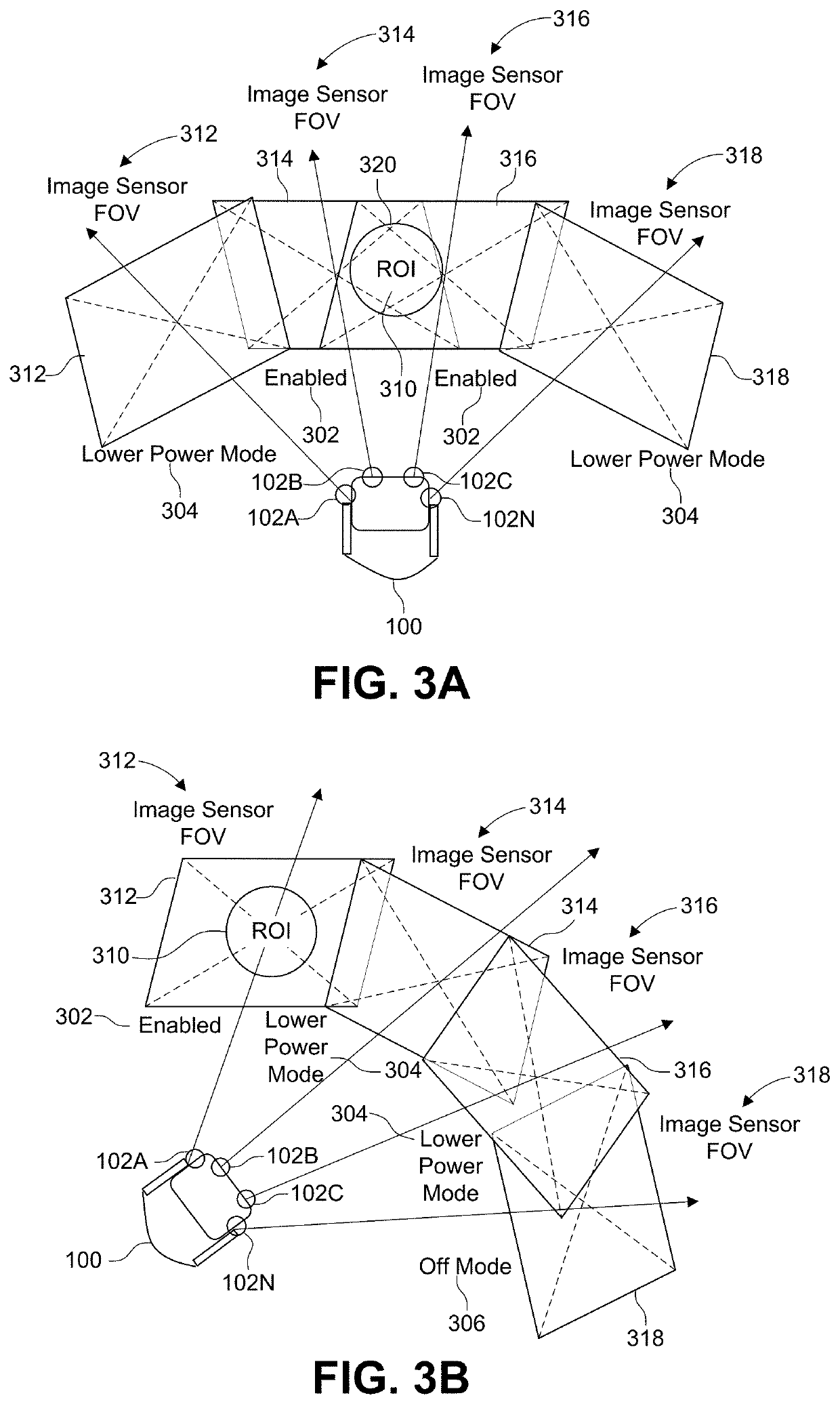
The patent text describes a method, computer-readable medium, and apparatus for adjusting the power modes of two image sensors in an electronic device based on the movement of the device and the area of interest (ROI). The first image sensor is always on and can detect the movement of the device and the ROI. When theROI moves out of the first image sensor's field of view (FOV), the method reduces the power mode of the first sensor and increases the power mode of the second sensor, which has a lower power cost than the first sensor. The second sensor captures additional images of the ROI. This allows for faster and more efficient detection of movement and can improve user experience.

Problems solved by technology

In many cases, the imaging, processing, and / or performance capabilities / results of the lower-power camera can be limited.

Method used


Image

  • Region of interest capture for electronic devices
  • Region of interest capture for electronic devices
  • Region of interest capture for electronic devices

Examples


Embodiment Construction

[0038]Certain aspects and embodiments of this disclosure are provided below. Some of these aspects and embodiments may be applied independently, and some of them may be applied in combination as would be apparent to those of skill in the art. In the following description, for the purposes of explanation, specific details are set forth in order to provide a thorough understanding of embodiments of the application. However, it will be apparent that various embodiments may be practiced without these specific details. The figures and description are not intended to be restrictive.

[0039]The ensuing description provides example embodiments only and is not intended to limit the scope, applicability, or configuration of the disclosure. Rather, the ensuing description of the exemplary embodiments will provide those skilled in the art with an enabling description for implementing an exemplary embodiment. It should be understood that various changes may be made in the function and arrangement ...


PUM


Abstract

Systems, methods, and non-transitory media are provided for capturing a region of interest (ROI) with a multi-camera system. An example method can include initializing image sensors of an electronic device, each image sensor being initialized in a lower-power mode having a lower power consumption than a higher-power mode supported by one or more of the image sensors; obtaining images captured by the image sensors in the lower-power mode; determining, based on the images, that an ROI in a scene is within a field-of-view (FOV) of a first image sensor from the image sensors; based on determining that the ROI is within the FOV of the first image sensor, decreasing the lower-power mode of one or more second image sensors to a power-off mode or an additional lower-power mode having a lower power consumption than the lower-power mode; and capturing, using the first image sensor, an image of the ROI.

Description

TECHNICAL FIELD[0001]The present disclosure generally relates to camera devices. For example, aspects of the present disclosure relate to controlling a region-of-interest camera capture for multi-camera devices.BACKGROUND[0002]Electronic devices are increasingly equipped with camera hardware to capture images and / or videos for consumption. For example, a computing device can include a camera (e.g., a mobile device such as a mobile telephone or smartphone including one or more cameras) to allow the computing device to capture a video or image of a scene, person, object, etc. The image or video can be captured and processed by the computing device (e.g., a mobile device, IP camera, extended reality device, connected device, security system, etc.) and stored and / or output for consumption (e.g., displayed on the device and / or another device). In some cases, the image or video can be further processed for effects (e.g., compression, image enhancement, image restoration, scaling, framerat...

Claims


Application Information

Patent Timeline
IPC IPC(8): H04N5/232H04N5/235H04N5/225
CPCH04N5/232411H04N5/2258H04N5/2353H04N5/23245H04N5/232945H04N5/144H04N23/651H04N23/65H04N23/667H04N23/6811H04N23/45H04N23/73H04N23/635
Inventor MAHBUB, UPALGUEST, DANIEL JAMESCURTIS, WALKERKANDHADAI, ANANTHAPADMANABHAN ARASANIPALAI
Owner QUALCOMM INC
Learn More