
Security camera system with multi-directional mount and method of operation

a camera system and multi-directional technology, applied in the near field of read/write/interrogation/identification systems, television systems, instruments, etc., can solve the problems of limited movement and/or available positions limited allowable movement and position range of the sensor modules, and often blind spots in the camera system. , to achieve the effect of preventing movement and/or vibration of the sensor module, reducing the cost of design and manufacturing, and reducing the cost of production

Active Publication Date: 2022-06-14
JOHNSON CONTROLS TYCO IP HLDG LLP
View PDF86 Cites 0 Cited by
  • Summary
  • Abstract
  • Description
  • Claims
  • Application Information

AI Technical Summary

Benefits of technology

This solution eliminates blind spots, reduces design complexity and costs, and shortens development cycles by allowing customizable field of view arrangements and independent manufacturing of base units and sensor modules, with enhanced image stitching and analytics capabilities.

Problems solved by technology

The problem with mechanical positioning systems in multi-sensor security cameras is that the movement and / or available positions of the sensor modules are limited by design factors such as the size of the mechanical gimbal and the necessity of predefined movement tracks and guides set for each axis.
Additionally, the wiring assembly, for carrying power and raw image data, between each sensor module and the image processing unit of the security camera system are bulky and often restrict the allowable range of movement and positions of the sensor modules.
As a result, these security camera systems often have blind spots, as their fields of view are limited by their mechanical design.
This results in high design and manufacturing costs and long development cycle times, all of which increase in proportion to the number of sensor modules required for each camera.

Method used


Image

  • Security camera system with multi-directional mount and method of operation
  • Security camera system with multi-directional mount and method of operation
  • Security camera system with multi-directional mount and method of operation

Examples


Embodiment Construction

[0027]The invention now will be described more fully hereinafter with reference to the accompanying drawings, in which illustrative embodiments of the invention are shown. This invention may, however, be embodied in many different forms and should not be construed as limited to the embodiments set forth herein; rather, these embodiments are provided so that this disclosure will be thorough and complete, and will fully convey the scope of the invention to those skilled in the art.

[0028]As used herein, the term “and / or” includes any and all combinations of one or more of the associated listed items. Further, the singular forms and the articles “a”, “an” and “the” are intended to include the plural forms as well, unless expressly stated otherwise. It will be further understood that the terms: includes, comprises, including and / or comprising, when used in this specification, specify the presence of stated features, integers, steps, operations, elements, and / or components, but do not pre...


PUM


Abstract

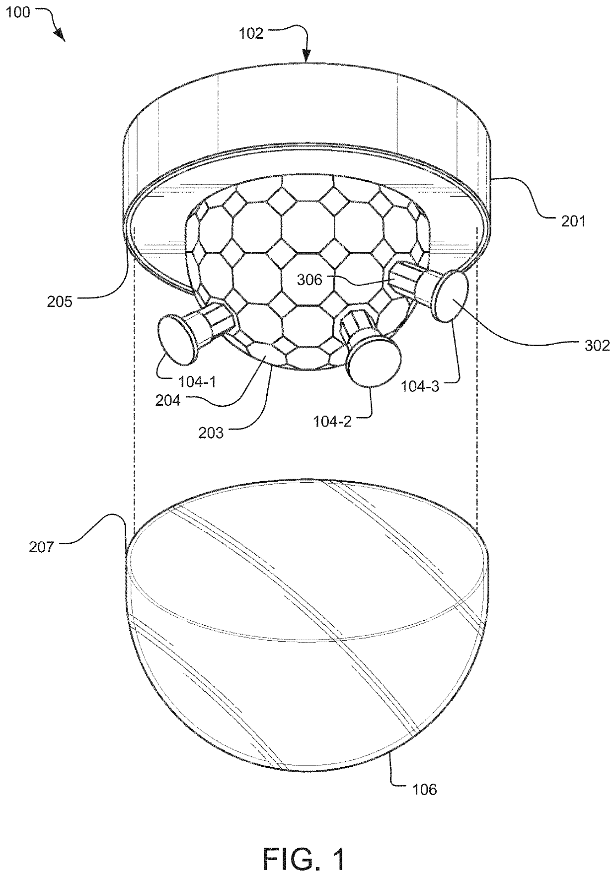
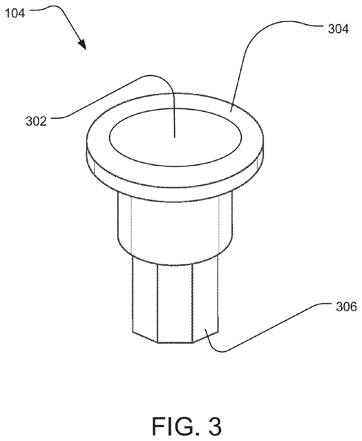
A security camera system includes a base unit and sensor modules for generating image data. The base unit includes several mounting sockets arranged at different elevational and azimuthal directions around the base unit, and the sensor modules attach, for example, magnetically, to the mounting sockets. Each mounting socket includes a socket ID, which is read by a reader module of the sensor modules and used to stitch together the image data from different sensor modules. The sensor modules are powered wirelessly via induction and communicate wirelessly with the base unit via wireless transceivers and antennas.

Description

BACKGROUND OF THE INVENTION[0001]Video surveillance, e.g., security, systems are often deployed in and around buildings as well as in metropolitan settings. Example buildings and metropolitan settings include schools, government buildings, commercial buildings, residential buildings, multi dwelling units, roads and highways, and town and city centers.[0002]These video security systems typically include surveillance, e.g., security, cameras that connect via a security network to a control system. Additional components include network video recorder (NVR) systems and monitors for displaying images such as video from the security cameras.[0003]The security cameras typically have a lenses and imager systems that are fixed, adjustable, or motorized. A fixed security camera will have the lens and imager system permanently fixed in a set position (i.e., lens and imager system cannot change position with respect to camera body). On the other hand, an adjustable security camera's lens and im...

Claims


Application Information

Patent Timeline
Patent Type & Authority Patents(United States)
IPC IPC(8): H04N5/247G08B13/196H04N5/225H04N5/232H04B5/00H04N23/90
CPCG08B13/19628G08B13/19632H04B5/0031H04B5/0037H04B5/0056H04N5/2258H04N5/2259H04N5/232H04N5/23241H04N23/45H04N23/58H04N23/65H04B5/77H04B5/79H04B5/24H04N23/60H04B5/72
Inventor SIU, PATRICK
Owner JOHNSON CONTROLS TYCO IP HLDG LLP
Learn More