
Material testing machine and radiation CT device

a testing machine and radiation ct technology, applied in the direction of instruments, material strength using steady bending force, tensile/compressive force, etc., can solve the problems of low versatility, difficult to accurately perform internal observation of the test piece tp, complex operation for performing material test, etc., to improve the accuracy of three-dimensional observation, avoid the effect of high cos

Active Publication Date: 2022-06-07
SHIMAZU TEKUNORISAAC
View PDF79 Cites 0 Cited by
  • Summary
  • Abstract
  • Description
  • Claims
  • Application Information

AI Technical Summary

Benefits of technology

The present invention aims to provide a material testing machine and a radiation CT device that can easily and quickly conduct material tests and improve the accuracy of radiation CT images. Additionally, the invention allows for easy attachment and removal of test pieces, reducing the complexity of the material testing process. The invention improves the durability of the material testing machine against load by erecting pillars, which creates an open space around the test piece. This makes it easier to put a hand or the like closer to the center of the machine for easy performance of test procedures without disassembling the machine.

Problems solved by technology

However, each conventional example having such a configuration has problems as follows.
Thus, it is extremely difficult to accurately perform internal observation of the test piece TP.
However, it is concerned that the material testing machine 105a is limited in the contents of a material test and has low versatility, and an operation for performing the material test is complicated and time-consuming.
Thus, it is difficult to obtain many kinds of data in a single material test, and work of disposing sensors and wires around the test piece TP is complicated.
Furthermore, since the test space is small and closed, usable test pieces are limited to extremely small ones, and it is difficult to perform a material test by using the test piece TP having a shape and a size conforming to a standard such as JIS standard or ISO standard.
As a result, the material test will take an enormous amount of time.
However, since it is difficult to ensure sufficient strength with the cylindrical member 121 having such a configuration, the material testing machine 105a is likely to deform due to a load.
Thus, it is also concerned that the upper limit of the magnitude of a load that can be applied to the test piece is low in the material testing machine 105a.

Method used


Image

  • Material testing machine and radiation CT device
  • Material testing machine and radiation CT device
  • Material testing machine and radiation CT device

Examples


Embodiment Construction

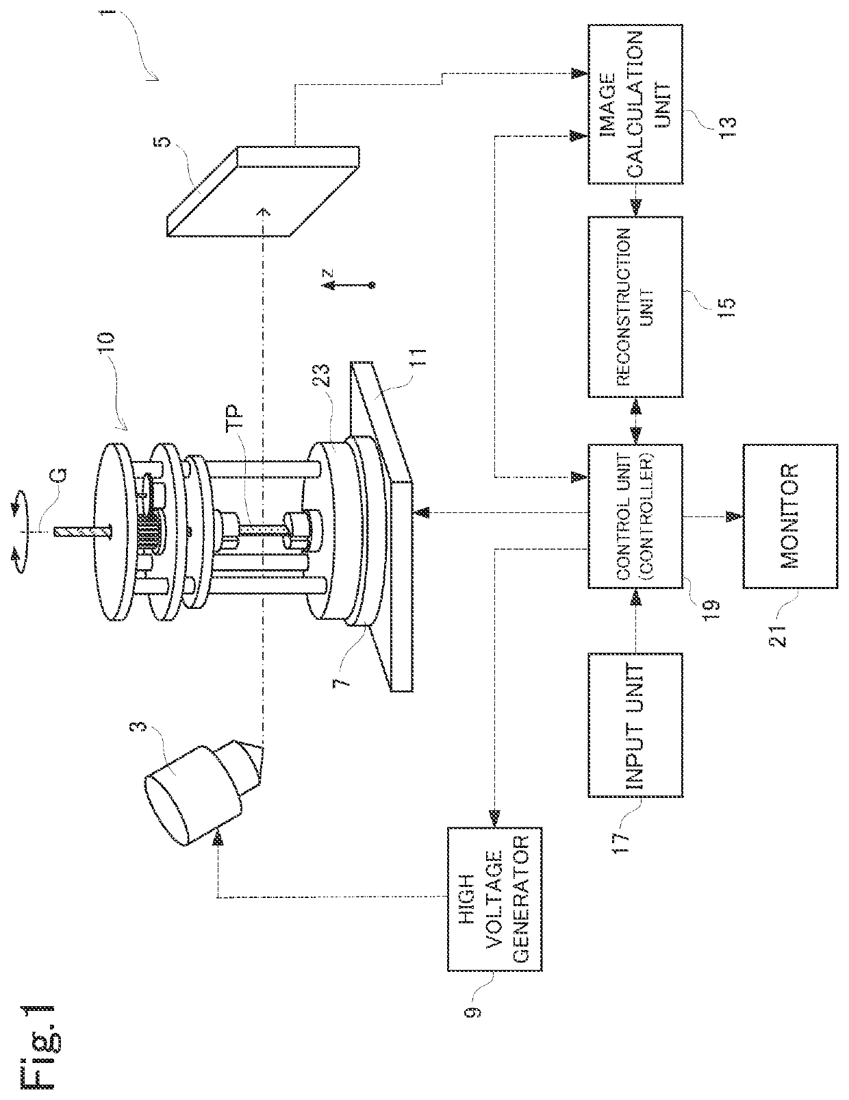
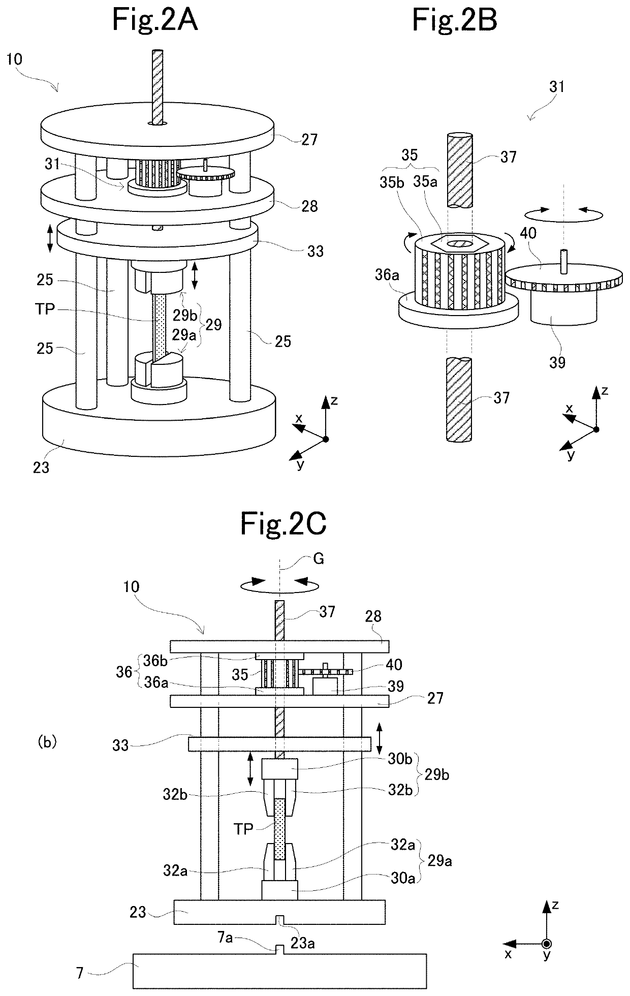
[0060]The following describes an embodiment of the present invention with reference to the accompanying drawings. The present embodiment exemplarily illustrates an X-ray CT device as an exemplary radiation CT device. FIG. 1 is a schematic diagram of an X-ray CT device 1 to which a material testing machine 10 according to the embodiment is applied. The present embodiment exemplarily describes a case in which a material test is performed by applying a tensile load to a test piece TP.

[0061]The X-ray CT device 1 includes an X-ray source 3, an X-ray detector 5, a rotary stage 7, and a high voltage generator 9. The X-ray source 3 and the X-ray detector 5 are disposed opposite to each other across the rotary stage 7. The rotary stage 7 is disposed between the X-ray source 3 and the X-ray detector 5 and rotatable about an axis orthogonal to the surface of the rotary stage 7. The rotary stage 7 rotates about an axis in a z direction denoted by reference sign G. It is possible to perform non-...


PUM

PropertyMeasurementUnit
rotation angleaaaaaaaaaa
angleaaaaaaaaaa
angle θ2aaaaaaaaaa

Abstract

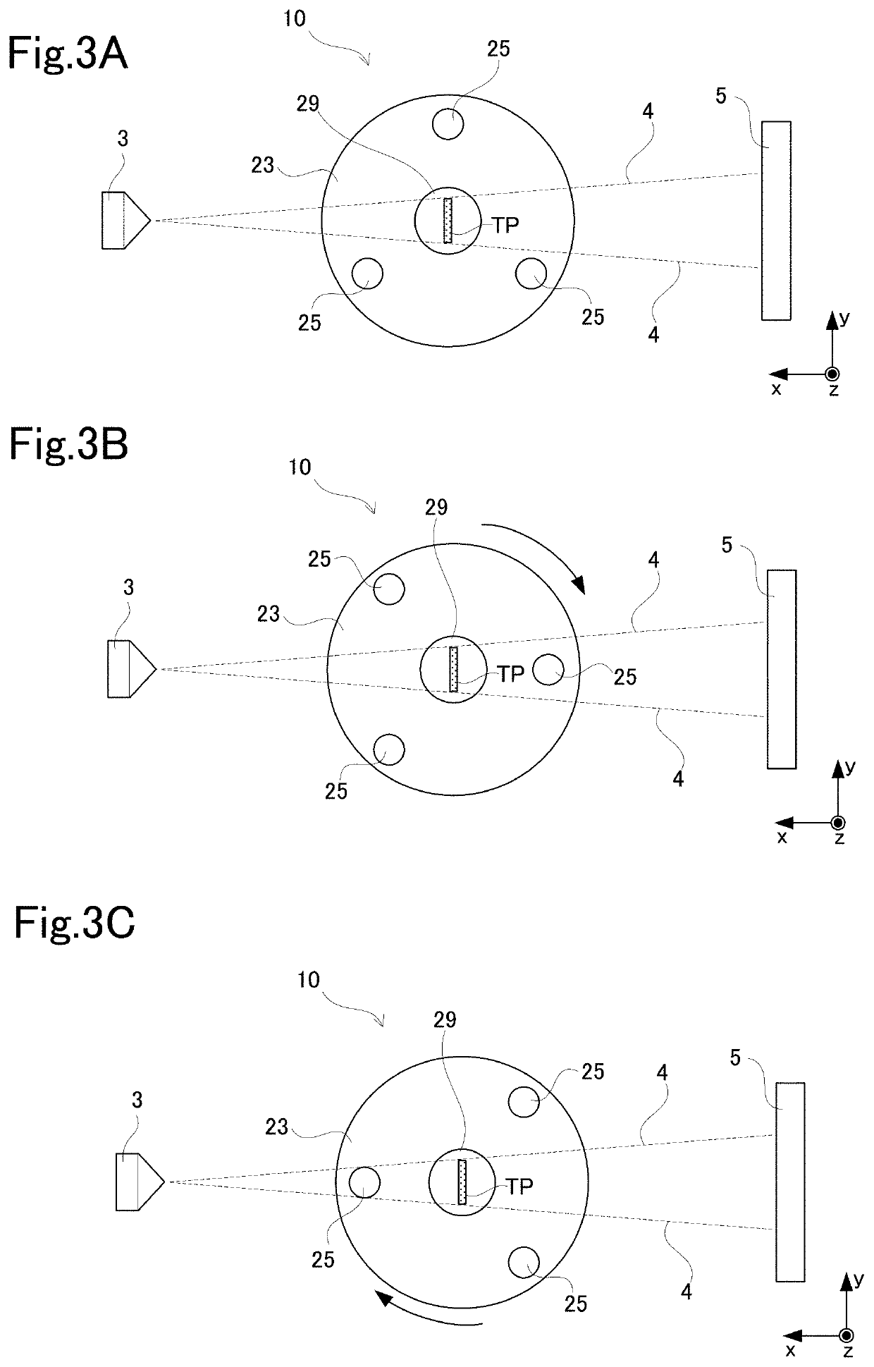
A grip portion configured to support a test piece is disposed at a central part of a base, and a plurality of pillars are erected on the base. A disposition and number of the plurality of pillars are adjusted so that an X-ray emitted from an X-ray source and transmitting through the test piece transmits through zero or one pillar in an optional image capturing direction. It is possible to avoid a situation in which an attenuation rate of the X-ray largely differs due to a difference in an image capturing direction to the test piece. Thus, it is possible to prevent a strong artifact from overlapping a CT image of the test piece in an X-ray CT image. Moreover, a material testing machine is supported by the plurality of pillars to have an accessible state around the test piece. This configuration facilitates handling of the material testing machine.

Description

BACKGROUNDTechnical Field[0001]The present invention relates to a material tester and a radiation CT apparatus capable of applying a load to a test piece and irradiating the test piece with radiation under the loaded condition to observe a radiation CT image of the test piece.Related Art[0002]In a material test of applying a load such as a tensile load, a compression load, a bending load, or a piercing load to a test piece to examine a property such as the strength of a material, X-ray fluoroscopy or X-ray CT image capturing is performed to observe the internal status of the test piece in some cases. As illustrated in FIG. 11, an X-ray CT device used for such a material test includes a rotary stage 103 between an X-ray source 101 and an X-ray detector 102, and a material testing machine 105 on which a test piece TP is disposed is placed on the rotary stage 103. A three-dimensional structure inside the test piece TP can be observed by executing X-ray fluoroscopy while rotating the ro...

Claims


Application Information

Patent Timeline
Patent Type & Authority Patents(United States)
IPC IPC(8): G01N23/04G01N23/046G01N23/06G01N23/083G01N23/087G01N23/18
CPCG01N23/046G01N23/04G01N23/083G01N23/087G01N23/18G01N2223/307G01N2223/309G01N3/00G01N3/08G01N3/20G01N2203/0016G01N2203/0023G01N2223/607G01N2203/0641G01N2203/0252G01N3/06
Inventor NAKAYAMA, TAKASHIDAIGEN, TOMOHIDETSUMAKI, NOBUYOSHI
Owner SHIMAZU TEKUNORISAAC
Learn More