
Methods and apparatus for determining the integrity of a bodily cavity

a technology of bodily cavity and integrity, applied in the field of uterine procedures, can solve problems such as the later discreditation of steam for this purpos

Active Publication Date: 2022-05-17
AEGEA MEDICAL
View PDF749 Cites 1 Cited by
  • Summary
  • Abstract
  • Description
  • Claims
  • Application Information

AI Technical Summary

Benefits of technology

[0010]A further improvement to the patency test is the real time control of the fluid flow rate. As an example, if the initial patency test result demonstrates a low or near threshold fluid flow rate, the fluid flow rate can be instantaneously increased in an attempt to unclog the lumen of the uterine ablation device. The lumen could be clogged with blood, tissue, or debris and this burst of increased fluid flow would be done in an attempt to free the lumen of the materials that are interfering with the patency test. If the increased fluid flow does not improve the flow rate in the patency test assessment, the uterine ablation device is removed from the patient and the device is inspected for clogging materials, and the entire process of the device insertion, with integrity and subsequent patency testing, is initiated. However, if the increased fluid flow is successful in removing the clogging materials in situ, the uterine cavity integrity test can repeated, with a subsequent confirmatory patency test, without the need for device removal and reinsertion. In this instance, the successful application of increased fluid flow resulted in less procedure time, less risk to the procedure, and patient discomfort by removing the need for device removal and reinsertion.
[0012]Further improvement to the accuracy and ease of applying the integrity system would be a benefit to the physician user, or making the entire system less expensive by the removal of accessory components that have been required in previously disclosed systems. The described systems demonstrate an improved integrity and patency test systems that either remove the requirement of an internal pressure sensor or an integrated flow meter within the system.
[0013]Also in practice, a system in which controlling the actual flow rate within the integrity and patency test system provides new benefits to the system that make the entire test more robust and accurate.

Problems solved by technology

The use of steam for this purpose was later discredited, apparently due to patient morbidity and mortality.
In addition, these tests can be used with hysteroscopic procedures since a perforation may not be readily detected even under direct vision.

Method used


Image

  • Methods and apparatus for determining the integrity of a bodily cavity
  • Methods and apparatus for determining the integrity of a bodily cavity
  • Methods and apparatus for determining the integrity of a bodily cavity

Examples


Embodiment Construction

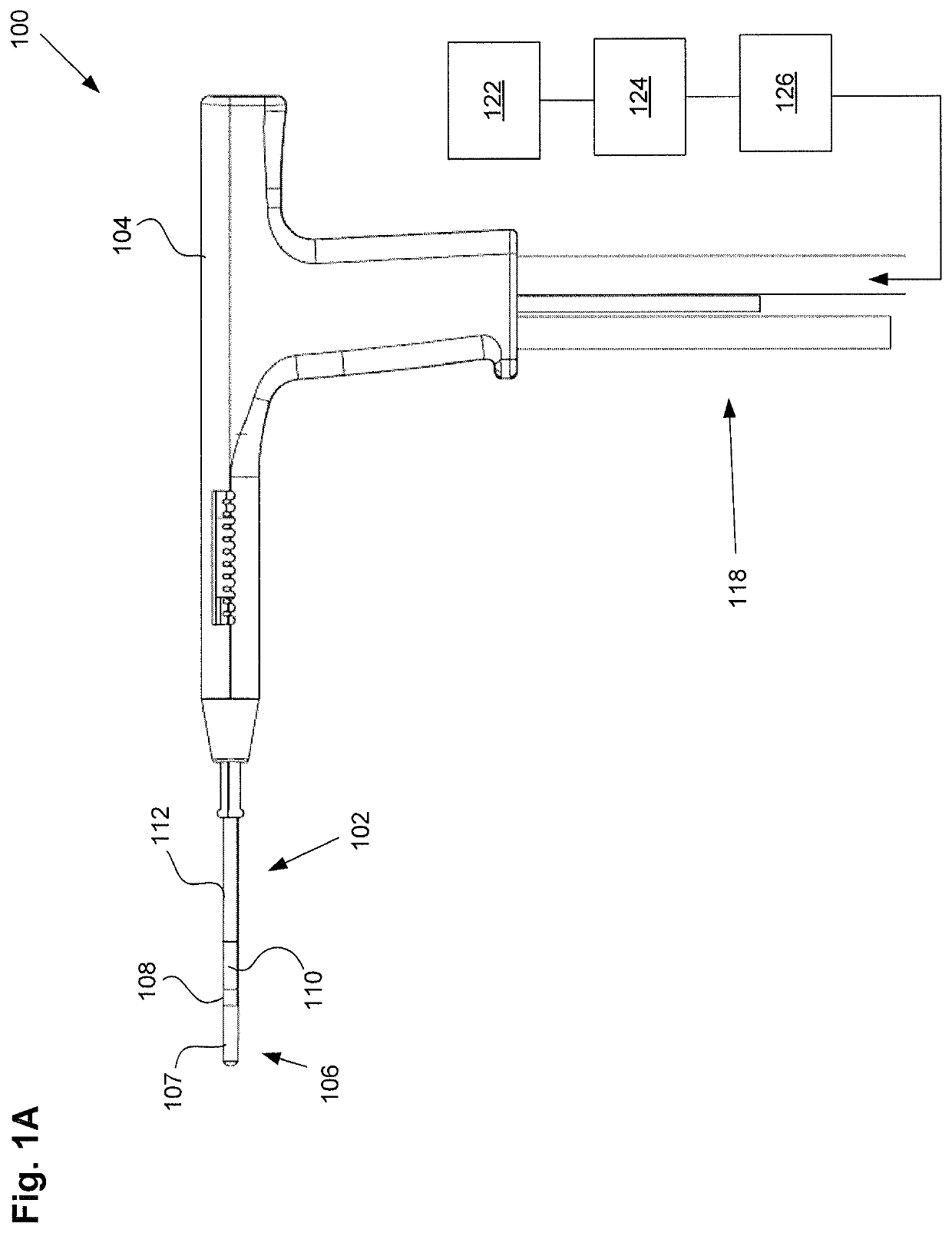
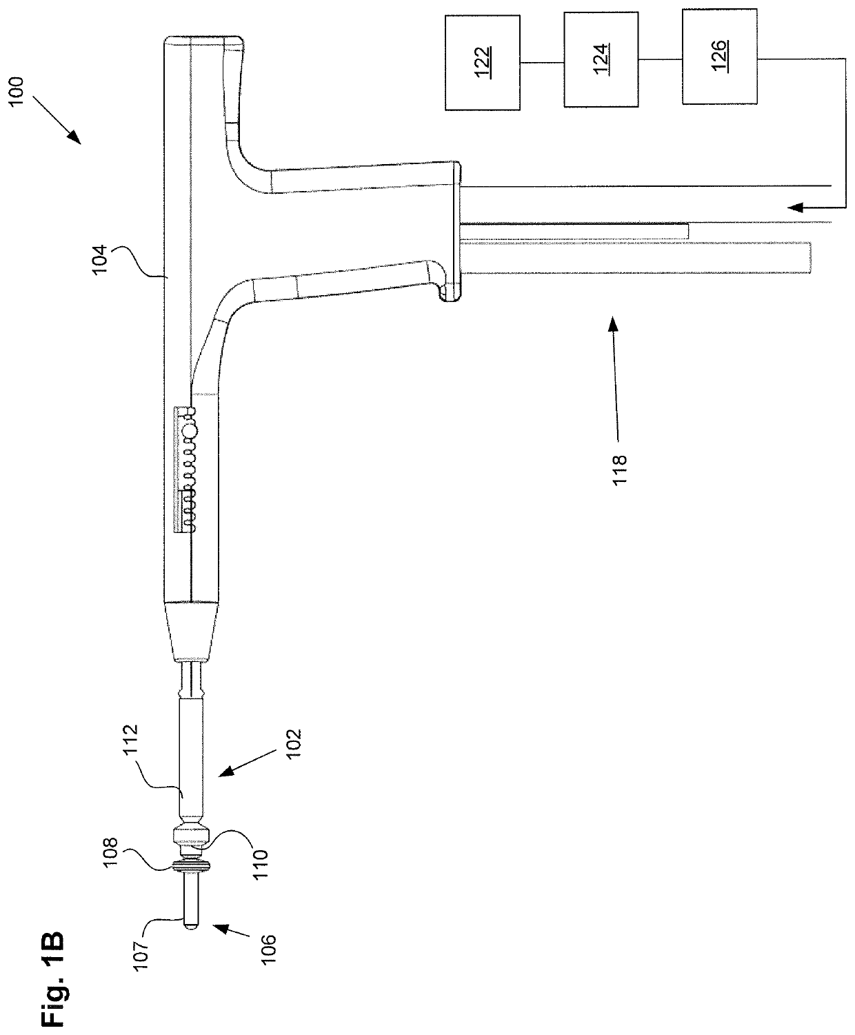
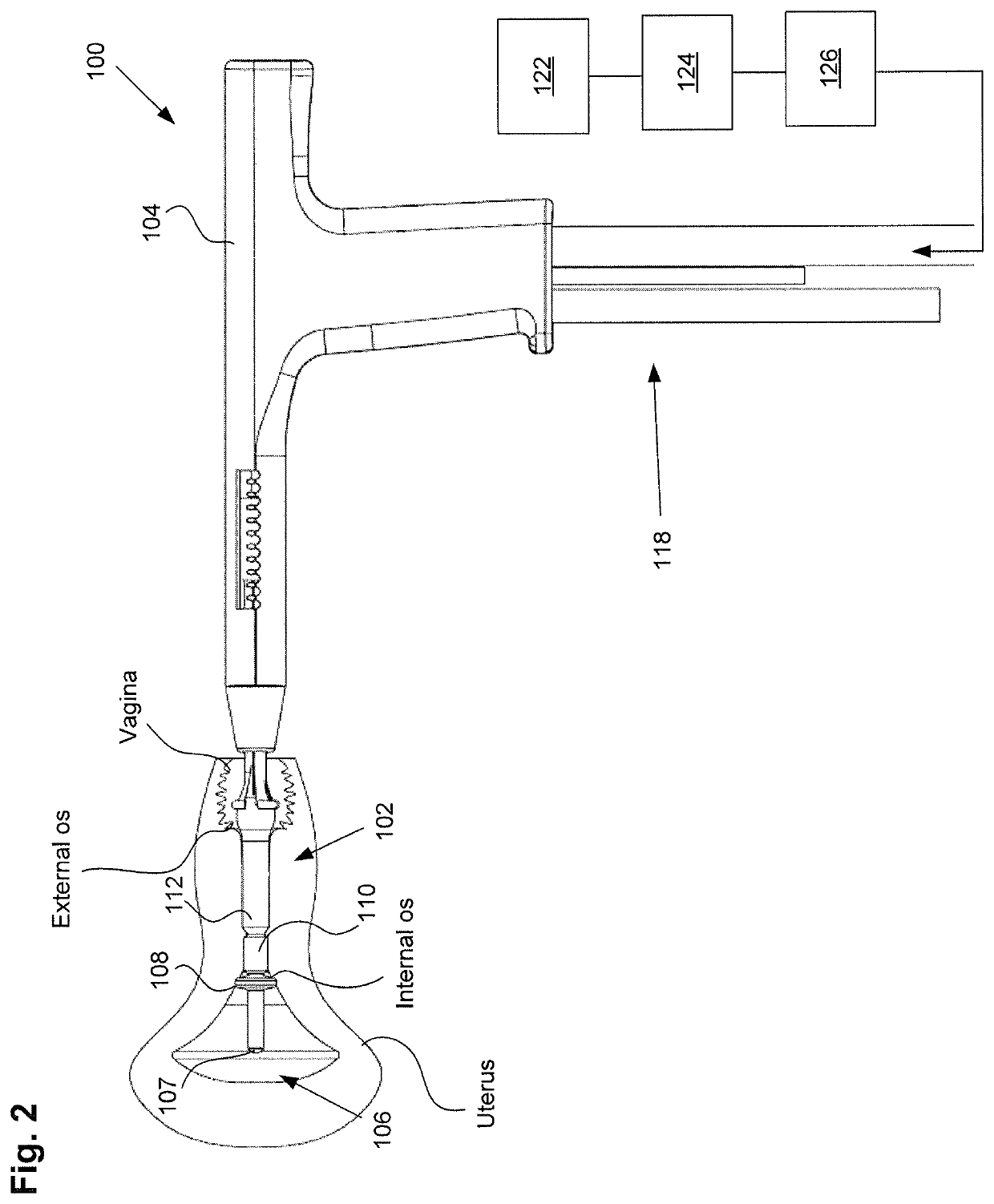
[0044]FIG. 1A illustrates a uterine ablation device 100 sized and configured to access the endometrium of a uterus and to deliver a heated vapor to the uterus to ablate uterine tissue. The device can be configured to ablate and treat the endometrial lining of the uterus as an alternative to hysterectomy for treating menorrhagia or other uterine diseases. In some embodiments, the device 100 can be configured to gain access to the uterus by being inserted through a cannula or hysteroscope. The device 100 can include shaft 102, handle 104, distal tip 106, vapor ports 107, distal anchor or distal balloon 108, central or sealing balloon 110, proximal or positioning balloon 112, and connection lumens 118, which can couple the uterine ablation device to a control system (not shown) comprising a computer, a vapor generation system, and mechanisms configured to inflate and deflate the balloons as well as control the delivery and removal of integrity gas / fluid and vapor from the device. Addit...


PUM


Abstract

A method and system of providing therapy to a patient's uterus is provided, which can include any number of features. The method can include the steps of inserting a uterine device into the uterus and performing a uterine integrity test to determine that the uterus is intact and not perforated. Systems for performing these methods with monitored flow rate and independent of patient height relative to the pressure source are also disclosed.

Description

CROSS REFERENCE TO RELATED APPLICATIONS[0001]This application claims the benefit under 35 U.S.C. 119 of U.S. Provisional Patent Application No. 62 / 297,643, filed Feb. 19, 2016, titled “Methods and Apparatus for Determining the Integrity of a Bodily Cavity”, and is a continuation-in-part of U.S. patent application Ser. No. 13 / 648,132, filed Oct. 9, 2012, titled “Integrity Testing Method and Apparatus for Delivering Vapor to the Uterus”, both of which are incorporated herein by reference.INCORPORATION BY REFERENCE[0002]All publications and patent applications mentioned in this specification are herein incorporated by reference to the same extent as if each individual publication or patent application was specifically and individually indicated to be incorporated by reference.FIELD OF THE DISCLOSURE[0003]The present disclosure generally relates to uterine procedures incorporating a distension media such as a fluid or a gas that could be used with endoscopic procedures or other visualiz...

Claims


Application Information

Patent Timeline
Patent Type & Authority Patents(United States)
IPC IPC(8): A61B5/00A61B18/00A61B18/04A61B17/42A61B90/00
CPCA61B5/4325A61B5/4839A61B18/00A61B18/04A61B2017/4216A61B2018/0022A61B2018/00559A61B2018/00577A61B2018/046A61B2090/0809
Inventor PELIKS, ROBERT BILGORGITTINGS, DARIN CHARLESMAGEN, HUGH EDWARDCHEE, URIEL HIRAM
Owner AEGEA MEDICAL
Learn More