Wind turbine

a wind turbine and wind power technology, applied in the field of wind power turbines, can solve the problems of complex use of j-tubes, high cost, error-prone and laborious, etc., and achieve the effect of avoiding overheating of cables

Active Publication Date: 2022-05-10
RWE RENEWABLES GMBH
View PDF8 Cites 0 Cited by
  • Summary
  • Abstract
  • Description
  • Claims
  • Application Information

AI Technical Summary

Benefits of technology

[0007]Based on this, the object was to avoid overheating of cables in a wind turbine or its foundation structure.
[0023]It is also proposed that the control element is arranged between the flow opening and the tube, between the flow opening and the interior of the hollow structural element, or on the outside of the flow opening. If the control element is arranged between the flow opening and the tube, the medium can flow into the tube through the flow opening and the control element. In this case, the flow of medium in the tube can be influenced by the control element. In particular, a flow volume through the tube can be increased compared to a natural flow, for example caused by wind. The control element can also be arranged inside the hollow structural element and thus be protected from environmental influences. If the control element is arranged on the outside of the flow opening, it can be maintained particularly easily. This applies in particular if the flow opening is located below the platform, since the opening is otherwise no longer accessible from the inside after the hollow structural element has been installed.
[0025]According to an embodiment, the control element can be a fan, in particular a blower. The fan can draw in outside air via the flow opening and blow it into the ventilation tube or the interior of the hollow structural element. The fan can draw in internal air via the flow opening and blow it out to the outside. The fan allows for increased air exchange. This promotes the cooling performance of the system. A fan, nozzle or propeller can also serve as a control element. In particular, a nozzle or propeller may be useful for water.
[0026]It is also proposed that the control element is a controllable flap and / or shutter. In this case, the flap and / or shutter can be opened or closed as well as moved, for example, stepwise or steplessly in at least two positions between an open position and a closed position. This allows the flow cross-section at the flow opening to be varied. Adjusting the flap and / or closure also has the effect that it can be cleared of incrustations and / or accretions and / or marine growth. Adjustment can be motorized, in particular by electric motor, or manual, in particular via sliding doors or lens shutters.
[0027]The flow opening can be closed by a grid or a net, which is permeable for the medium but impermeable for larger objects such as flotsam or animals. This prevents debris or animals from entering the interior of the hollow structural element. In addition, the flow openings above the Lowest Astronomical Tide (LAT) can be angled downward on the outside to prevent rainwater from entering.

Problems solved by technology

However, the use of J-tubes is complex, error-prone and cost-intensive, so that solutions are being sought to dispense with them.
However, due to an increased number of cables, especially when several wind turbines are connected to a substation, temperature problems may occur within a monopile.
Due to ohmic losses, Joule heat is generated in the cables.

Method used


Image

  • Wind turbine
  • Wind turbine
  • Wind turbine

Examples


Embodiment Construction

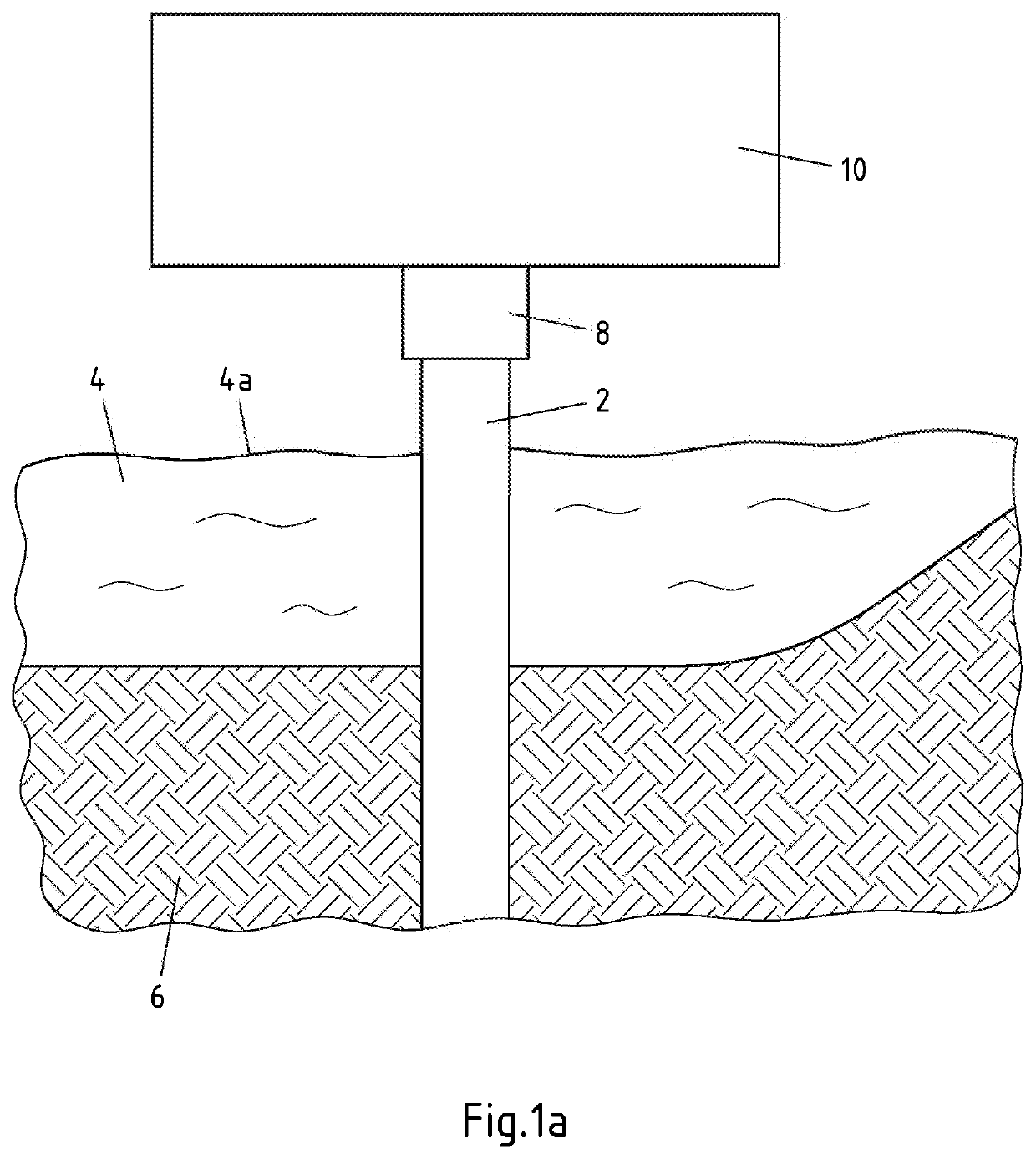
[0057]FIG. 1a shows a monopile 2 as a hollow structural element. The monopile 2 is founded on the seabed 6 in open sea 4. The monopile 2 protrudes beyond LAT 4a and is connected to a turbine of a wind turbine, for example a sub-station 10, via a transition piece 8.

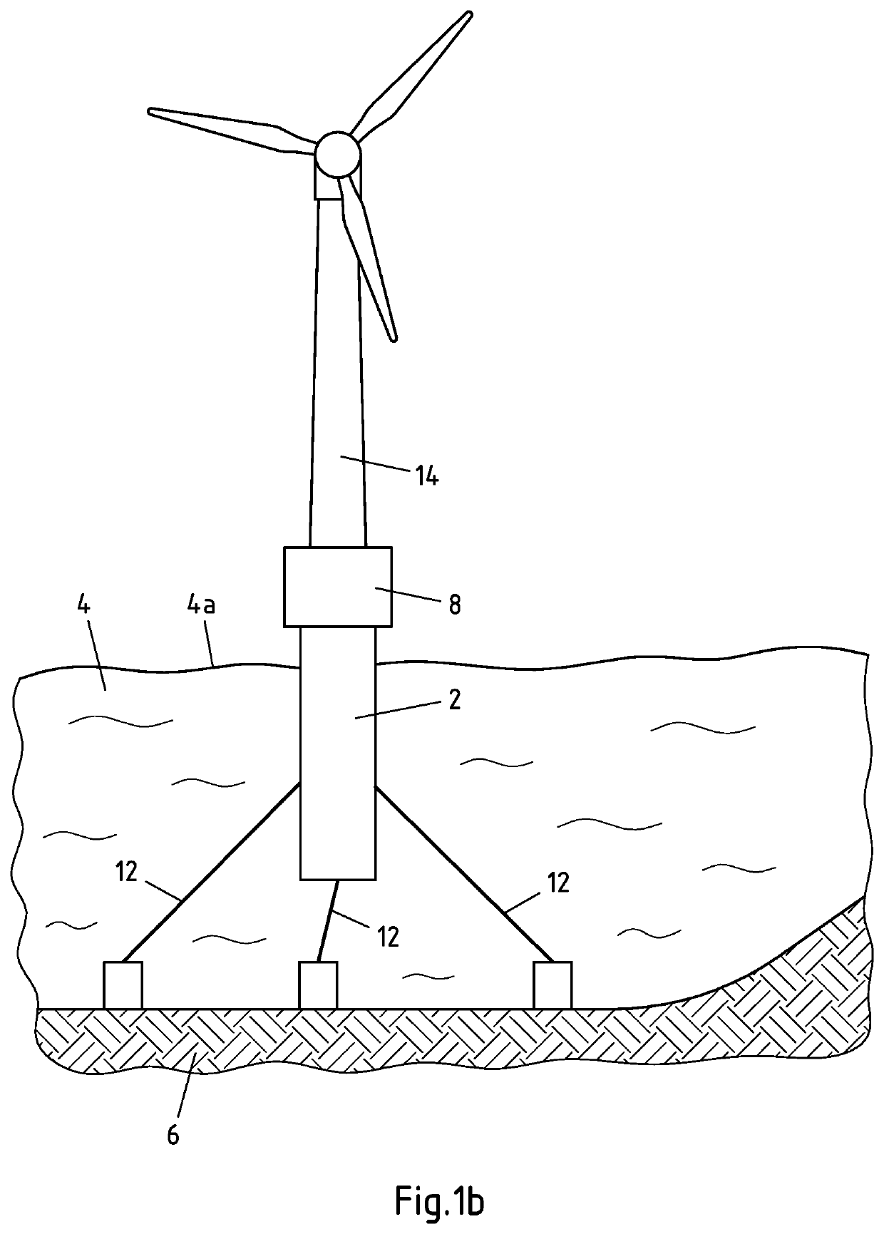
[0058]Another hollow structure element is shown in FIG. 1b. Here, too, a monopile 2 is provided, which, however, is floating and is founded in the seabed 6 via anchors 12. By way of example, it is shown that another tower 14 is attached to the transition piece 8, for example supporting a wind turbine.

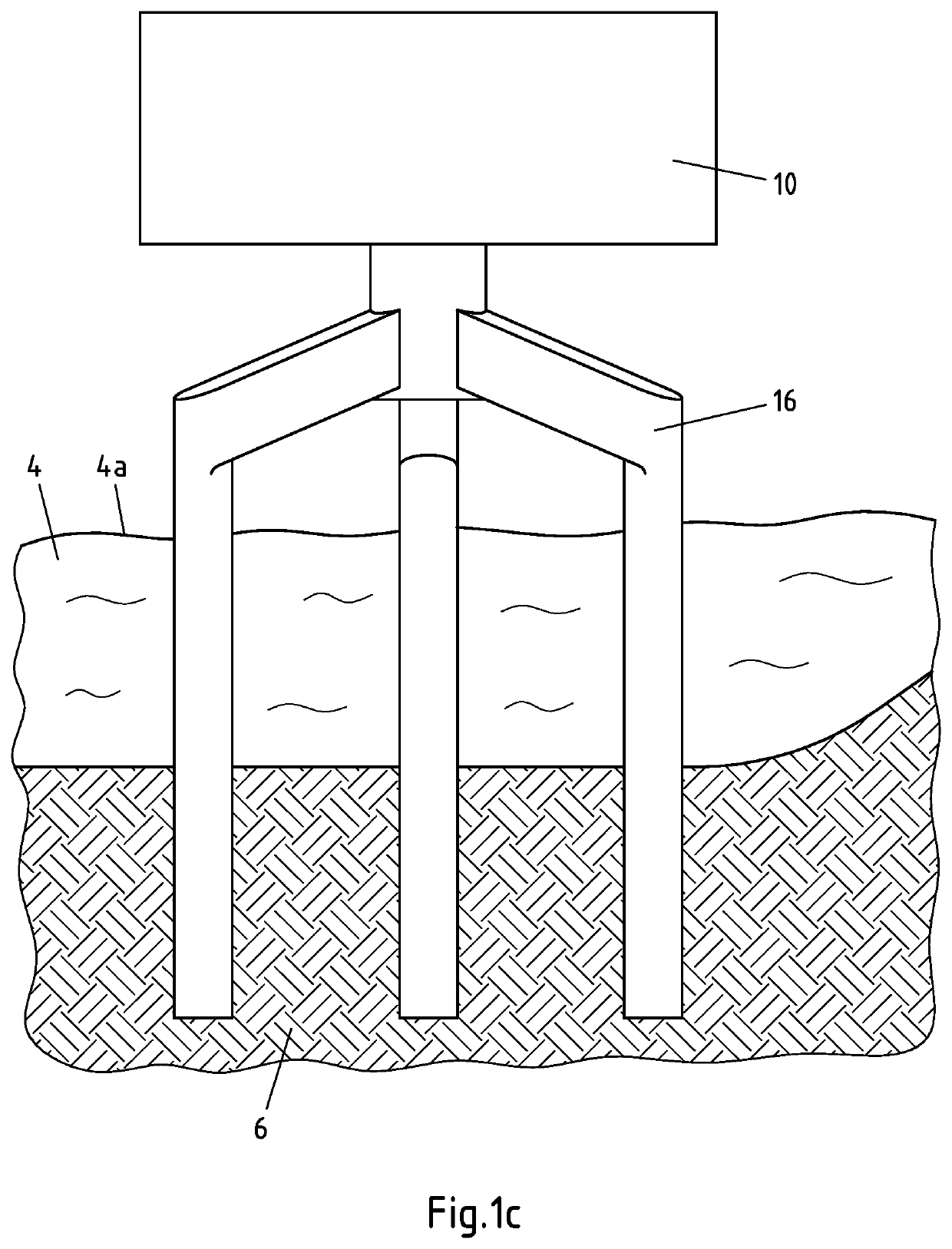
[0059]Another possible foundation of a hollow structural element is shown in FIG. 1c. Here, a tripile 16 serves as a support for a sub-station 10 and is founded in the ground 6.

[0060]These and other hollow structural elements as supports for wind turbines, for example wind turbines or substations, are suitable for the present arrangement of a cooling system.

[0061]FIG. 2 shows a monopile 2 which is founded in the ground 6. Abov...


PUM


Abstract

A wind turbine, in particular an offshore wind turbine includes at least one hollow structural element, at least one cable inlet arranged in a bottom region of the hollow structural element. A first platform is arranged inside the hollow structural element, above the bottom region. At least one flow opening is arranged in the shell surface of the hollow structural element and penetrating the shell surface. At least one active control element is flow-connected to the flow opening to affect a media exchange between the interior of the hollow structural element and the exterior of the hollow structural element.

Description

CROSS-REFERENCE TO RELATED PATENT APPLICATIONS[0001]This patent application is a continuation of International Application No. PCT / EP2019 / 077044, filed on Oct. 7, 2019, which claims the benefit of priority to German Patent Application No. 10 2018 125 323.0, filed Oct. 12, 2018, the entire teachings and disclosures of both applications are incorporated herein by reference thereto.FIELD OF INVENTION[0002]The application relates to a wind turbine, in particular an offshore wind turbine.BACKGROUND[0003]Wind farms, in particular offshore wind farms, usually have to be connected to a power grid via a transformer station. A transformer station can be located directly at a wind turbine or as a transformer station within the wind farm. In offshore wind farms, a monopile is a common design for the foundation structure of a wind turbine. A monopile may have cable entries for submarine cables to connect the wind turbines to each other and / or to a transformer station.[0004]Among other things, su...

Claims


Application Information

Patent Timeline
Patent Type & Authority Patents(United States)
IPC IPC(8): F03D13/25F03D80/60F03D80/80F03D9/25
CPCF03D13/25F03D80/60F03D80/85F03D9/255F05B2240/95F05B2260/20F05B2270/303F03D13/20E02B2017/0091E04H12/08E04H12/003Y02E10/727Y02E10/728Y02E10/72
Inventor OBERMEYER, SEBASTIANKLUGKIST, JÜRGENSCHLÜTER, THORSTENRUNGE, JÖRN
Owner RWE RENEWABLES GMBH
Why Eureka
Try Eureka