Headlamp control device

a control device and headlamp technology, applied in semiconductor devices, light sources, transportation and packaging, etc., can solve the problems of driver's pupils contracting and becoming smaller, the driver's ability to visually recognize the road state, and the road state deteriorating

Active Publication Date: 2022-05-10
MAZDA MOTOR CORP
View PDF6 Cites 0 Cited by
  • Summary
  • Abstract
  • Description
  • Claims
  • Application Information

AI Technical Summary

Benefits of technology

[0006]The technology disclosed herein improves a visual recognition ability of a driver in an environment where the visibility of the road state deteriorates, to suppress that the visibility of the road state forward of the vehicle deteriorates.

Problems solved by technology

Meanwhile, according to the present inventors' diligent research, it has been discovered that one cause of the visibility of the road state forward of the vehicle deteriorating during rain at night is that the pupils of the driver contract and become smaller.
When the pupils become smaller, since the reflected light from the road becomes less likely to enter into the pupils, the driver's ability to visually recognize the road state worsens, and therefore, the visibility of the road state forward of the vehicle deteriorates.
However, since the driver's pupils stay small, a large improvement in the driver's visual recognition ability cannot be expected.
Particularly, the image captured by the camera will not improve the ability to recognize the road state distant from the vehicle greatly.

Method used


Image

  • Headlamp control device
  • Headlamp control device
  • Headlamp control device

Examples


embodiment 1

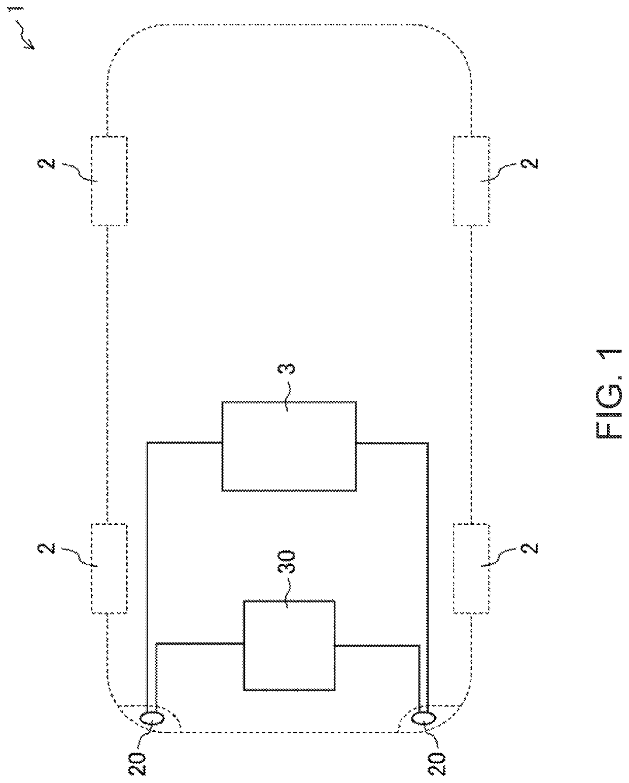
[0031]FIG. 1 illustrates a vehicle 1 having a pair of headlamps 20 controlled by a control device according to Embodiment 1 (a body-system ECU 30 described later). The vehicle 1 is a four-wheel automobile in which two wheels (here, front wheels) among four wheels 2 located symmetrically in the left-and-right direction are driven by a drive unit (not illustrated). Therefore, the vehicle 1 moves (travels). In the following description, front, rear, left, right, up, and down of the vehicle 1 are simply referred to as front, rear, left, right, up, and down, respectively.

[0032]The pair of headlamps 20 are provided at the left and the right in a front part of the vehicle 1, and illuminate the road ahead of the vehicle 1. Although detailed illustration is omitted, each headlamp 20 is disposed so as to continue to a front fender of the vehicle 1. The headlamp 20 is electrically connected with a battery 3. The headlamp 20 is turned on when electric power is supplied from the battery 3.

[0033]...

embodiment 2

[0063]Hereinafter, Embodiment 2 is described in detail with reference to the accompanying drawings. Note that in the following description, the same reference characters are assigned to common parts to Embodiment 1 to omit the detailed description.

[0064]As illustrated in FIG. 9, Embodiment 2 differs from Embodiment 1 in that a detected result of a steering torque sensor 14 is inputted into the ECU 30. Moreover, Embodiment 2 differs from Embodiment 1 in a condition for the headlamp controlling module 32 executing the brightness adjusting control. In detail, the headlamp controlling module 32 does not execute the brightness adjusting control, when the traveling scene determining module 31 determines that the vehicle 1 is turning to the right or to the left at an intersection. When the vehicle 1 turns to the right or turns to the left at the intersection, the driver needs to carefully watch the road state near the vehicle rather than the road state distant from the vehicle. If the brig...

embodiment 3

[0076]Below, Embodiment 3 is described in detail with reference to the accompanying drawings. Note that in the following description, the same reference characters are assigned to common parts to Embodiments 1 and 2 to omit the detailed description.

[0077]Embodiment 3 differs from Embodiments 1 and 2 in a condition for the headlamp controlling module 32 executing the brightness adjusting control. In detail, when the traveling scene determining module 31 determines that an amount of environment light around the vehicle being more than a given amount, the headlamp controlling module 32 does not execute the brightness adjusting control. This is because, if there is much environment light around the vehicle, the driver's visual recognition ability hardly improves by the brightness adjusting control. That is, even if the brightness adjusting control is executed, the driver is hardly able to recognize the brightness gradient of the light of the headlamp 20, since the effect of the environm...


PUM


Abstract

A headlamp control device configured to control a headlamp which illuminates forward of a vehicle, is provided. The device includes a visibility detector configured to detect visibility of a road state forward of the vehicle, and a headlamp controlling module configured to control brightness of the headlamp. The headlamp controlling module is able to adjust light emitted from the headlamp so that a brightness gradient that is a difference of brightness of a part distant from the vehicle and brightness of a part closer to the vehicle is changed. When a deterioration in the visibility is detected, the headlamp controlling module executes a brightness adjusting control in which the brightness gradient is increased by making the brightness of the part closer to the vehicle higher than the brightness of the part distant from the vehicle, as compared with the brightness gradient when the deterioration in the visibility is not detected.

Description

TECHNICAL FIELD[0001]The technology disclosed herein belongs to a technical field related to a headlamp control device.BACKGROUND OF THE DISCLOSURE[0002]Conventionally, in an environment where the visibility of a vehicle driver worsens such as during rain at night, a technology which enables the driver to recognize a road state has been proposed.[0003]For example, JP2000-238594A discloses a driving support device for displaying an image captured by a camera which is installed in a vehicle and fetches information on an environment outside the vehicle on a display of a car navigation system or a head mounted display, when it determines that it is difficult to visually recognize a vehicle position on the road.[0004]Meanwhile, according to the present inventors' diligent research, it has been discovered that one cause of the visibility of the road state forward of the vehicle deteriorating during rain at night is that the pupils of the driver contract and become smaller. That is, at nig...

Claims


Application Information

Patent Timeline
Patent Type & Authority Patents(United States)
IPC IPC(8): B60Q1/14F21S41/65F21S41/141H05B45/10H05B47/125F21Y115/10F21W102/13F21W102/20
CPCB60Q1/143B60Q1/1423F21S41/141F21S41/65H05B45/10H05B47/125B60Q2300/054B60Q2300/134B60Q2300/314B60Q2300/33F21W2102/13F21W2102/20F21Y2115/10Y02B20/40H05B47/11H05B47/105
Inventor KUSUMOTO, SHIMPEITAKENOUCHI, KUMIKO
Owner MAZDA MOTOR CORP
Why Eureka
Try Eureka