
Method for the model-based open loop and closed loop control of an internal combustion engine

a technology of model-based control and internal combustion engine, which is applied in the direction of electrical control, exhaust treatment, mechanical equipment, etc., can solve the problems of high adaptation effort, achieve the effect of reducing complexity, reducing the maximum conversion rate, and reducing the degree of freedom

Active Publication Date: 2022-05-03
ROLLS ROYCE SOLUTIONS GMBH
View PDF13 Cites 2 Cited by
  • Summary
  • Abstract
  • Description
  • Claims
  • Application Information

AI Technical Summary

Benefits of technology

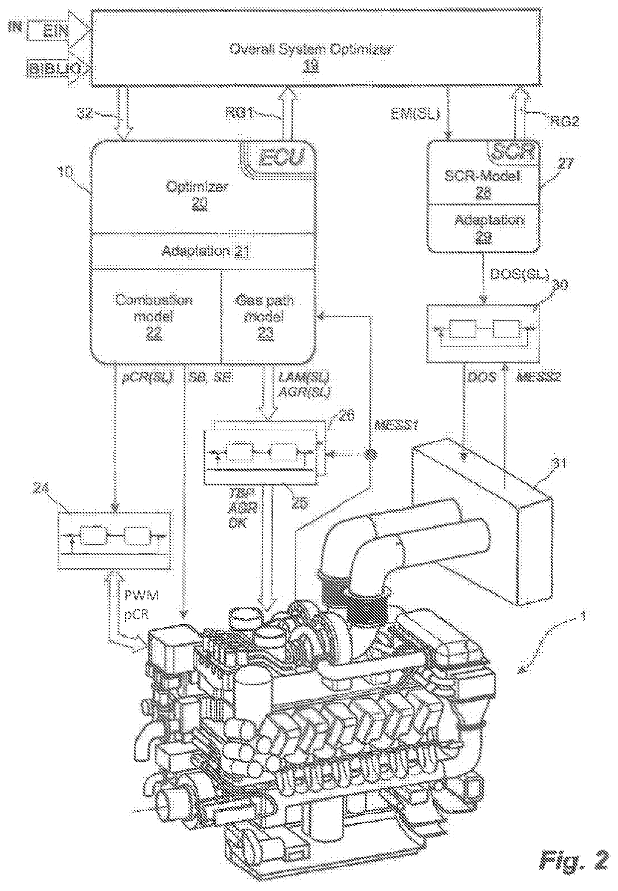
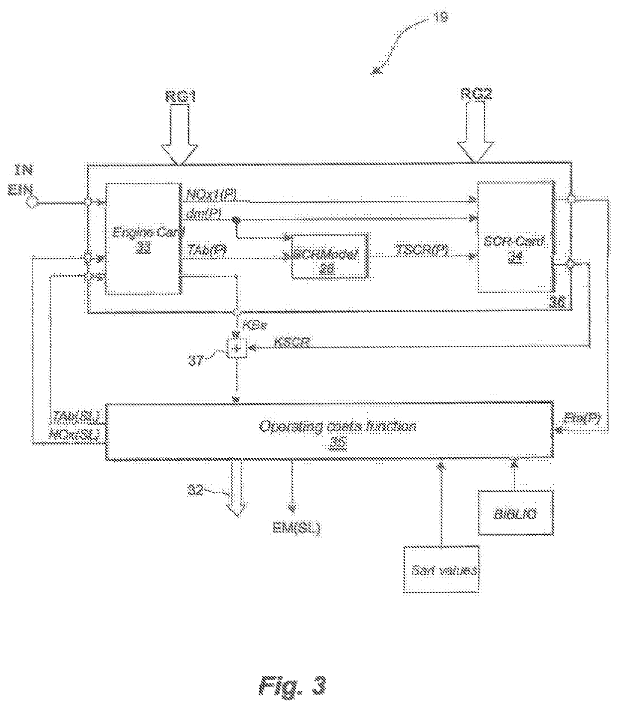
[0010]In addition to the known advantage of modularization, namely a reduction in complexity, a greater degree of freedom is achieved by the invention. For example, a higher exhaust gas temperature setpoint is maintained in the event of load dumping, due to which the SCR catalytic converter achieves a higher maximum conversion rate. So that the operating costs of the overall system are nevertheless minimized, the new operating point of the combustion engine is specified in the engine characteristics diagram by the overall system optimizer in such a way that lower specific fuel consumption results. This means that the increased costs of the reducing agent are offset by a lower specific fuel consumption. Due to the use of standardized interfaces, new components can be integrated without problems into the hierarchical control system, for example, a radiator control system. In the case of an integrated radiator control, the cost of operating the cooling system is converted into fuel consumption. The overall system optimizer then calculates if stronger cooling of the overall system would result in a lower overall operating cost. Special attention was directed to a low data exchange between the overall system optimizer and the individual components, as a result of which, as already previously mentioned, the complexity of the system description and the computational efforts are reduced. Thus, cards for the overall system optimizer are created for the behavior of the subordinate components. The system behavior, in regard to the considered interfaces is described therein. In other words, on the plane of the overall system optimizer detailed knowledge is not required from the subordinate components.

Problems solved by technology

The plurality of these characteristic curves / performance graphs and the interaction of the characteristic curves / performance graphs among each other; however, cause a high adaptation effort.

Method used


Image

  • Method for the model-based open loop and closed loop control of an internal combustion engine
  • Method for the model-based open loop and closed loop control of an internal combustion engine
  • Method for the model-based open loop and closed loop control of an internal combustion engine

Examples


Embodiment Construction

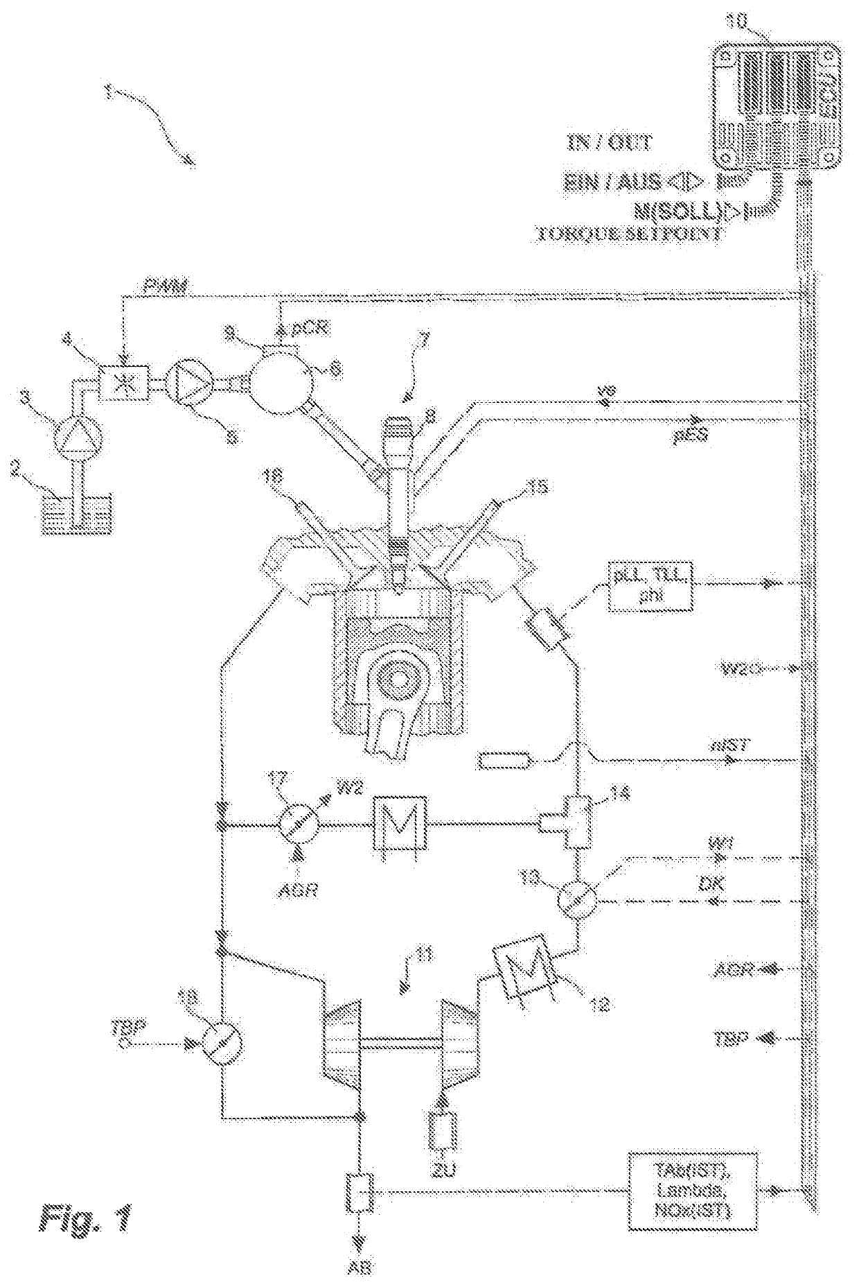
[0031]Exemplary embodiments provided according to the present invention are illustrated by the drawings and now referring to FIG. 1 there is shown a system diagram of an electronically controlled internal combustion engine 1 with a common rail system. The abbreviations used in the figures are presented below, and are referred to herein. The common rail system includes the following mechanical components: a low pressure pump 3 to move fuel from a fuel tank 2, a variable suction throttle 4 to influence the fuel volume flow, a high pressure pump 5 to move fuel under increased pressure, a rail 6 for the storing of fuel and injectors 7 for injecting the fuel into the combustion chambers of internal combustion engine 1. The common rail system may optionally also be equipped with individual accumulators, wherein for example, an individual accumulator 8 is integrated into injector 7 as an additional buffer volume. The additional functionality of the common rail system is assumed to be known...


PUM


Abstract

A method for regulation of an internal combustion engine with an SCR catalytic converter in which the operating point of the engine is predefined by an engine control unit and the operating point of the catalytic converter is predefined by an SCR control unit. An overall system quality measure is calculated by an optimizer in accordance with fed back values of the engine control unit and fed back values of the SCR control unit, by changing the default values for the engine control unit and the SCR control unit, the optimizer minimizes the overall system quality measure for a prediction horizon regarding operating costs. On the basis of the minimized overall system quality measure the optimizer sets the default values for the engine control unit and the default values for the SCR control unit as decisive for setting the operating point of the engine and the catalytic converter.

Description

CROSS REFERENCE TO RELATED APPLICATIONS[0001]This is a continuation of PCT application No. PCT / EP2019 / 075391, entitled “METHOD FOR THE MODEL-BASED OPEN-LOOP AND CLOSED-LOOP CONTROL OF AN INTERNAL COMBUSTION ENGINE WITH AN SCR CATALYTIC CONVERTER”, filed Sep. 20, 2019, which is incorporated herein by reference.BACKGROUND OF THE INVENTION1. Field of the Invention[0002]The current invention relates to a method for model-based control and regulation of an internal combustion engine with a Selective Catalytic Reduction (SCR) catalytic converter in which the operating point of the internal combustion engine is predefined by means of an engine control unit and the operating point of the SCR catalytic converter is predefined by means of an SCR control unit.2. Description of the Related Art[0003]The behavior of an internal combustion engine is significantly determined by way of an engine control unit, based on an operator request. In the software of the engine controller, relevant characteri...

Claims


Application Information

Patent Timeline
Patent Type & Authority Patents(United States)
IPC IPC(8): F02D41/14F02D41/02F01N3/20
CPCF02D41/1406F01N3/208F02D41/0235F02D41/146F02D41/1445F02D41/1446F01N2610/02F02D2041/1412F02D2041/1433F02D2200/0625Y02T10/12F02D41/0285F02D2041/1437F01N2900/1402F01N2900/1404F01N2900/0601F01N2900/1621F01N2900/0414Y02A50/20
Inventor GRAICHEN, KNUTBERGMANN, DANIELGEISELHART, ROMANNIEMEYER, JENSREMELE, JÖRGHARDER, KARSTENSPÄDER, TIM
Owner ROLLS ROYCE SOLUTIONS GMBH
Learn More