
Synchronous side lobe jamming method for electronic attack

a side lobe and electronic attack technology, applied in the field of synchronous side lobe jamming method for electronic attack, can solve the problems of preventing radar from normally detecting, exposing the use of high power and target's performing jamming, and conventional side lobe jamming, etc., to achieve less power and effectively cope

Active Publication Date: 2022-04-19
AGENCY FOR DEFENSE DEV
View PDF15 Cites 0 Cited by
  • Summary
  • Abstract
  • Description
  • Claims
  • Application Information

AI Technical Summary

Benefits of technology

[0015]Therefore, an aspect of the detailed description is to provide a synchronous side lobe jamming method for an electronic attack, which is capable of jamming a low power synchronous side lobe by overcoming the limitations of the existing noise side lobe jamming technique.
[0016]Another aspect of the detailed description is to provide a synchronous side lobe jamming method for an electronic attack, which may overcome a difference in arrival time to a radar between main and side lobe reflected signals without jamming exposure.
[0024]As described above, according to the synchronous side lobe jamming method for an electronic attack according to the embodiment of the present invention, it is possible to perform effective side lobe jamming with less power than noise jamming. Also, it is possible to overcome a radar arrival time difference between the main lobe and the side lobe without jamming exposure. Thus, it is possible to effectively cope with not only the conventional tracking radar but also multiple long-range search radars in which more side lobe signals than main lobe signals are received by a jammer. Furthermore, it is possible to secure a core technology of a remote support electronic attack that may protect power (platform) of an ally infiltrating into an enemy air defense network.

Problems solved by technology

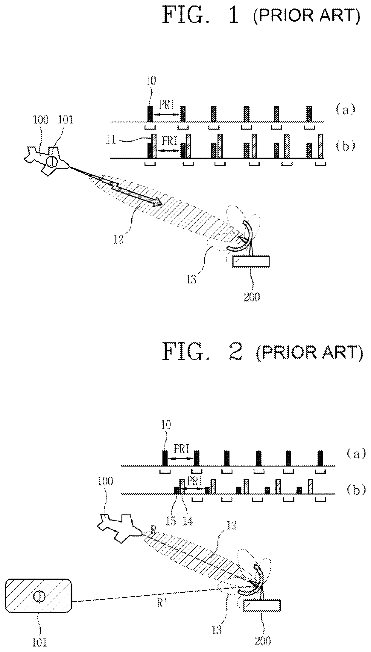
Meanwhile, jamming, which is an electromagnetic disturbance technique, generates radiowave interference with a larger output than a reflected wave of the radar, thereby preventing the radar from normally detecting information of the target.
The main lobe noise jamming is to send a high-power noise signal so that the search and tracking radar cannot detect information of the target itself.
This is effective for both the search radar and the tracking radar but disadvantageous in that the use of high power and target's performing jamming are exposed.
Therefore, most of the conventional side lobe jamming is mainly noise jamming.
However, noise jamming requires a higher power than synchronous jamming and has a disadvantage of being easily exposed.

Method used


Image

  • Synchronous side lobe jamming method for electronic attack
  • Synchronous side lobe jamming method for electronic attack
  • Synchronous side lobe jamming method for electronic attack

Examples


Embodiment Construction

[0033]Description will now be given in detail of preferred embodiments of the present invention with the accompanying drawings.

[0034]In addition, since the present invention can be modified into various forms and have various embodiments, specific embodiments will be illustrated in the drawings and detailed description thereof will be given. It should be understood, however, that the invention is not intended to be limited to the specific embodiments, but includes all modifications, equivalents, and alternatives falling within the spirit and scope of the invention.

[0035]It will be understood that although the terms first, second, etc. may be used herein to describe various elements, these elements should not be limited by these terms. These terms are generally only used to distinguish one element from another. For example, without departing from the scope of the present invention, the first component may be referred to as a second component, and similarly, the second component may a...


PUM


Abstract

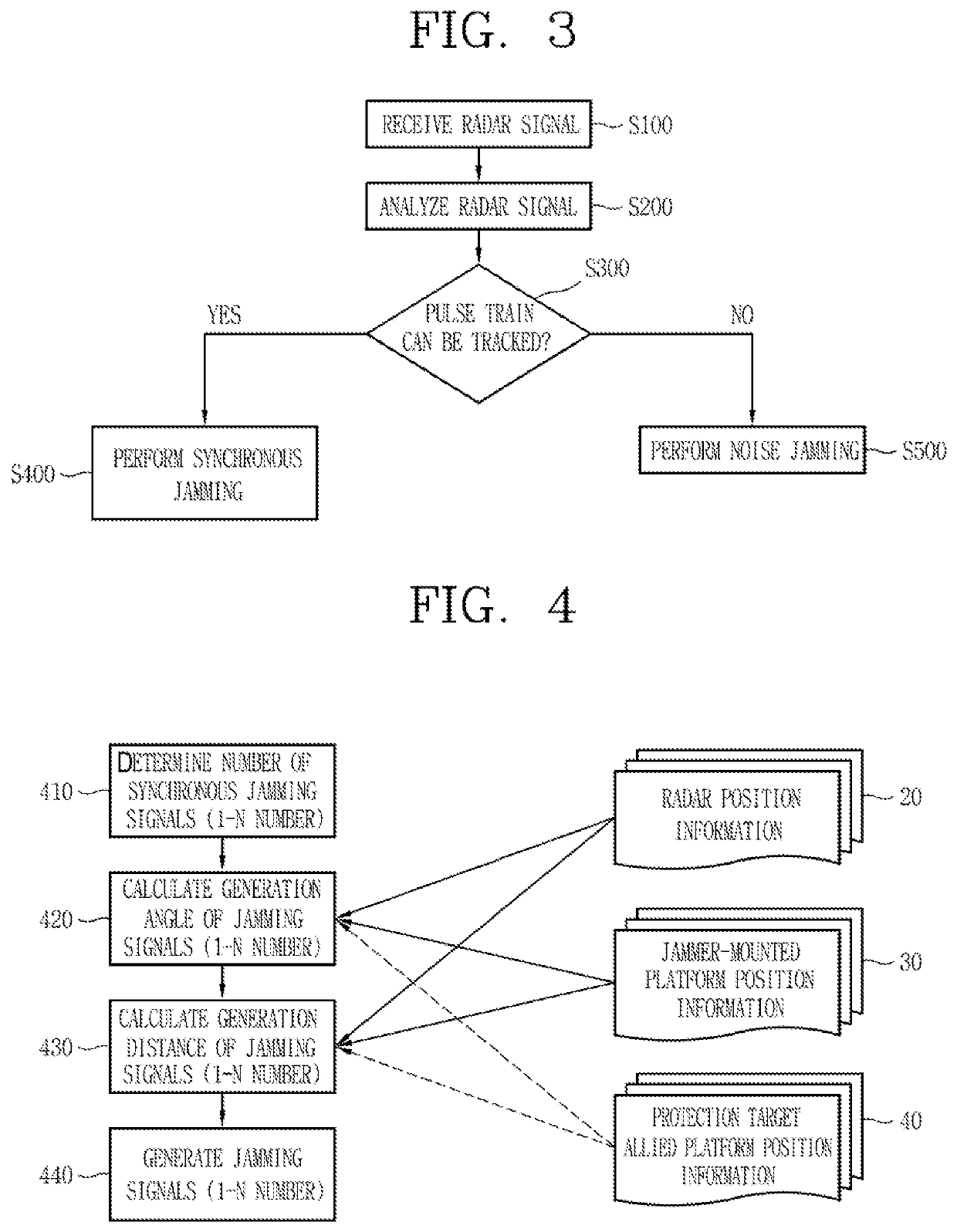
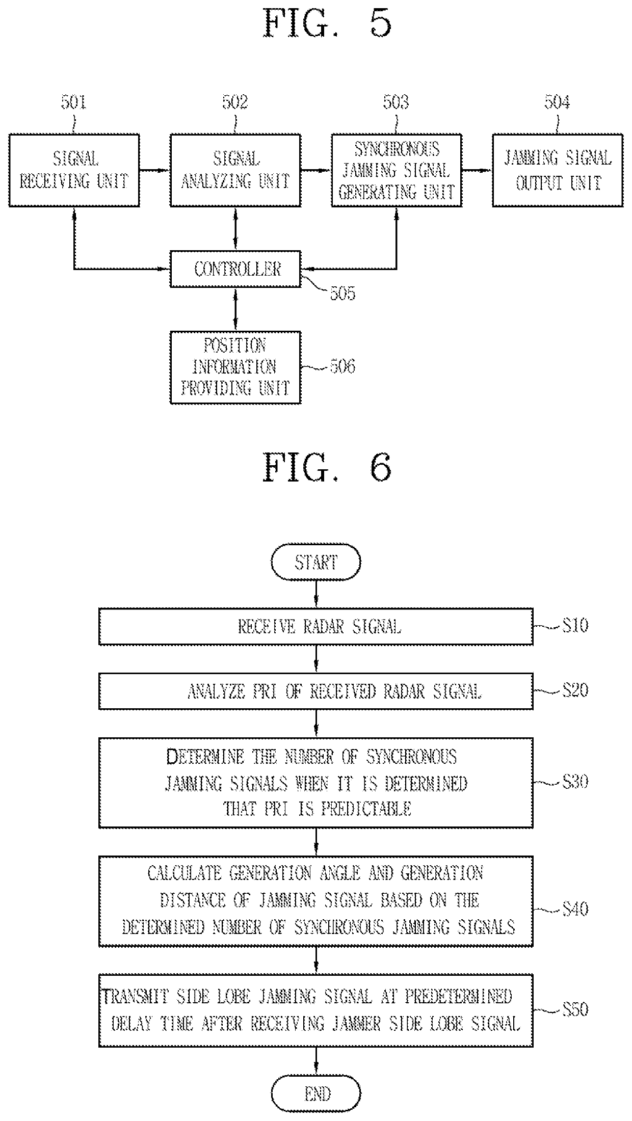
A synchronous side lobe jamming method for an electronic attack is disclosed. The method includes receiving a radar signal from an external radar; determining the number of synchronous jamming signals based on pulse repetition interval (PRI) characteristic of the received radar signal; generating a synchronous side lobe jamming signal by calculating a generation angle and a generation distance of each of the synchronous jamming signals; and transmitting the generated synchronous side lobe jamming signal to the radar at a predetermined delay time after a jammer receives a side lobe signal.

Description

CROSS-REFERENCE TO RELATED APPLICATION[0001]Pursuant to 35 U.S.C. § 119(a), this application claims the benefit of earlier filing date and right of priority to Korean Application No. 10-2019-0001363, filed on Jan. 4, 2019, the contents of which is incorporated by reference herein in its entirety.BACKGROUND OF THE DISCLOSURE1. Field of the Disclosure[0002]The present disclosure relates to a synchronous side lobe jamming method for an electronic attack.2. Background of the Disclosure[0003]A radar transmits an electromagnetic wave to track a target object (hereinafter, referred to as a “target”) and receives an electromagnetic wave reflected from the target. The radar then measures received time, direction, frequency and the like of the reflected electromagnetic wave to detect and track information about the target (e.g., distance, direction, velocity, etc.).[0004]Types of radar are broadly divided into a search radar that detects roughly a direction of a target in all directions or di...

Claims


Application Information

Patent Timeline
Patent Type & Authority Patents(United States)
IPC IPC(8): G01S7/38
CPCG01S7/38G01S7/021
Inventor KIM, SOYEONKIM, SANGWONLEE, DONGKEUNJEONG, UNSEOB
Owner AGENCY FOR DEFENSE DEV
Learn More