
Actuators for converting rotational input to axial output

a technology of axial output and actuators, which is applied in the direction of friction gearings, instruments, gearings, etc., can solve the problems of adding weight and complexity to the overall system, and achieve the effect of greater rotational stiffness

Active Publication Date: 2022-04-19
THE BF GOODRICH CO
View PDF13 Cites 0 Cited by
  • Summary
  • Abstract
  • Description
  • Claims
  • Application Information

AI Technical Summary

Benefits of technology

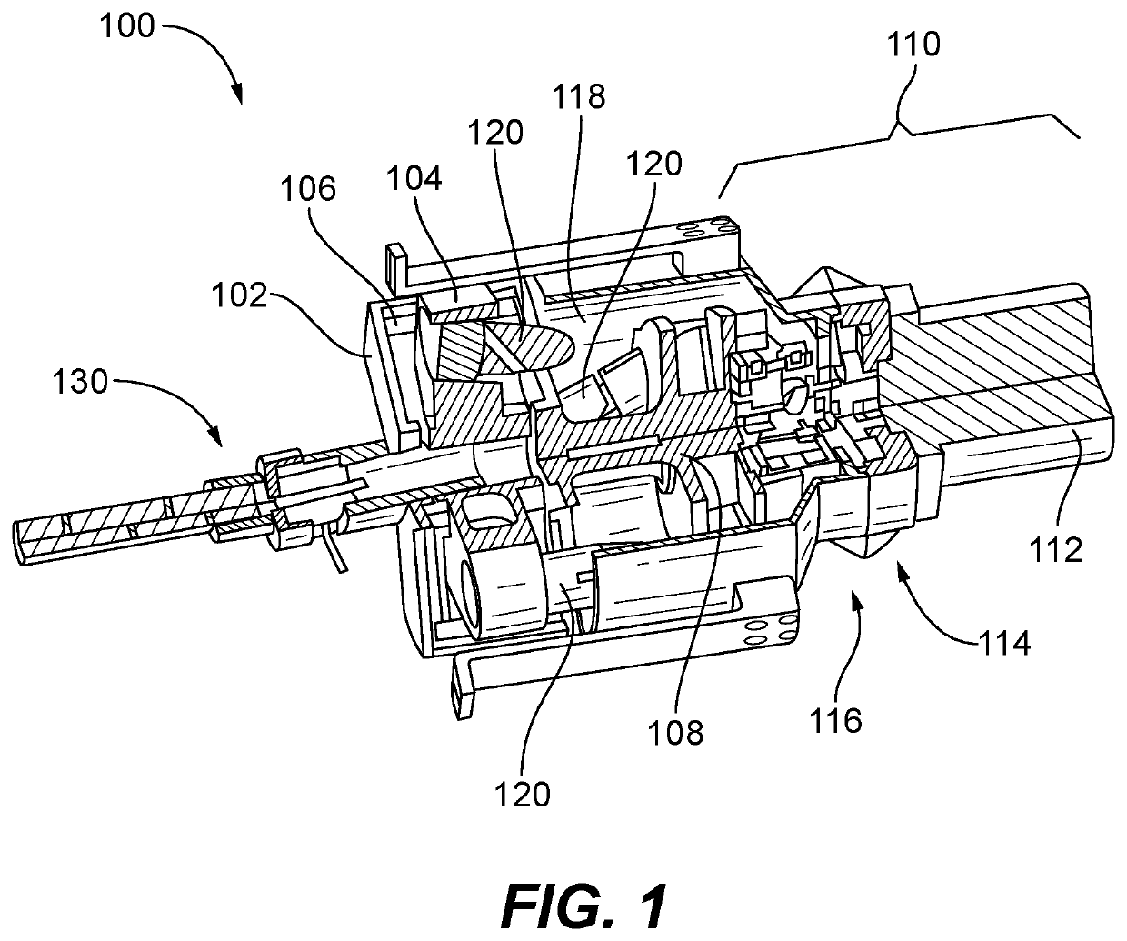
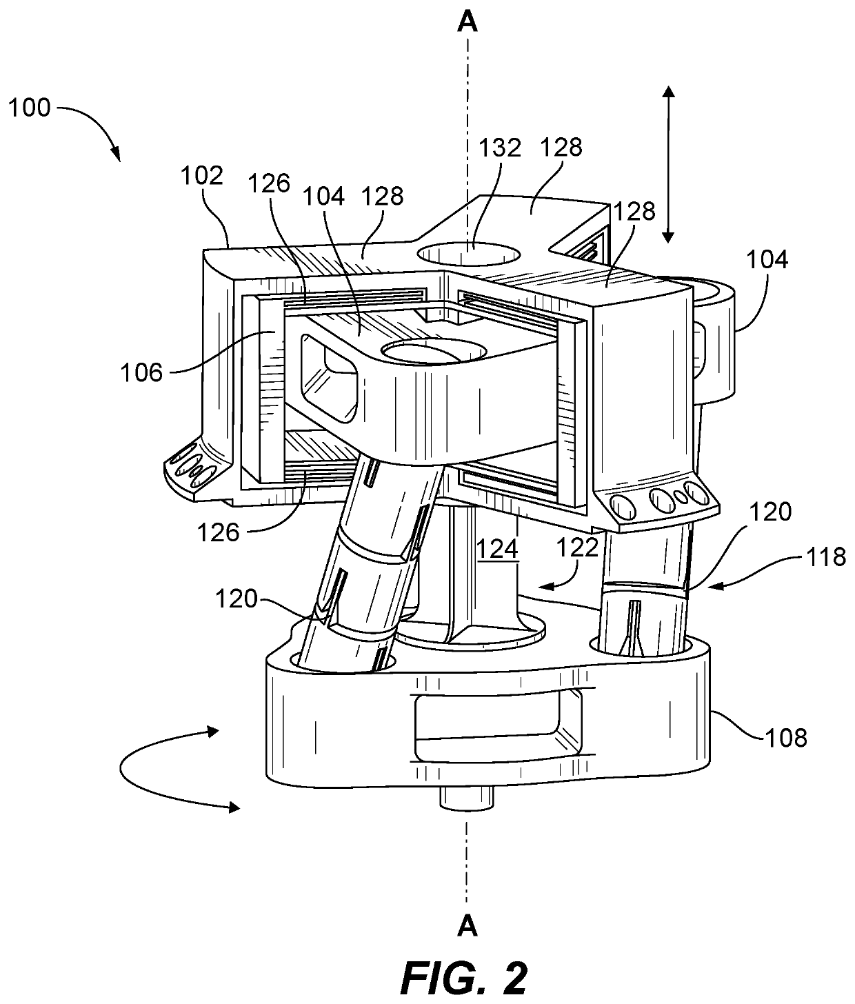
[0006]The flexure assembly can include a plurality of blades flexibly supporting the carriage from the frame. The plurality of blades can provide flexibility for axial movement of the carriage relative to the frame along the axis and provide rigidity in other directions. The flexure assembly can include three arms circumferentially spaced apart from one another. Each arm can have a plurality of the blades flexibly supporting the carriage from the frame. The flexure assembly can have a rotational stiffness greater than that of the cross-blade flexures.

Problems solved by technology

Such designs include a large number of parts, thereby adding weight and complexity to the overall system.

Method used


Image

  • Actuators for converting rotational input to axial output
  • Actuators for converting rotational input to axial output
  • Actuators for converting rotational input to axial output

Examples


Embodiment Construction

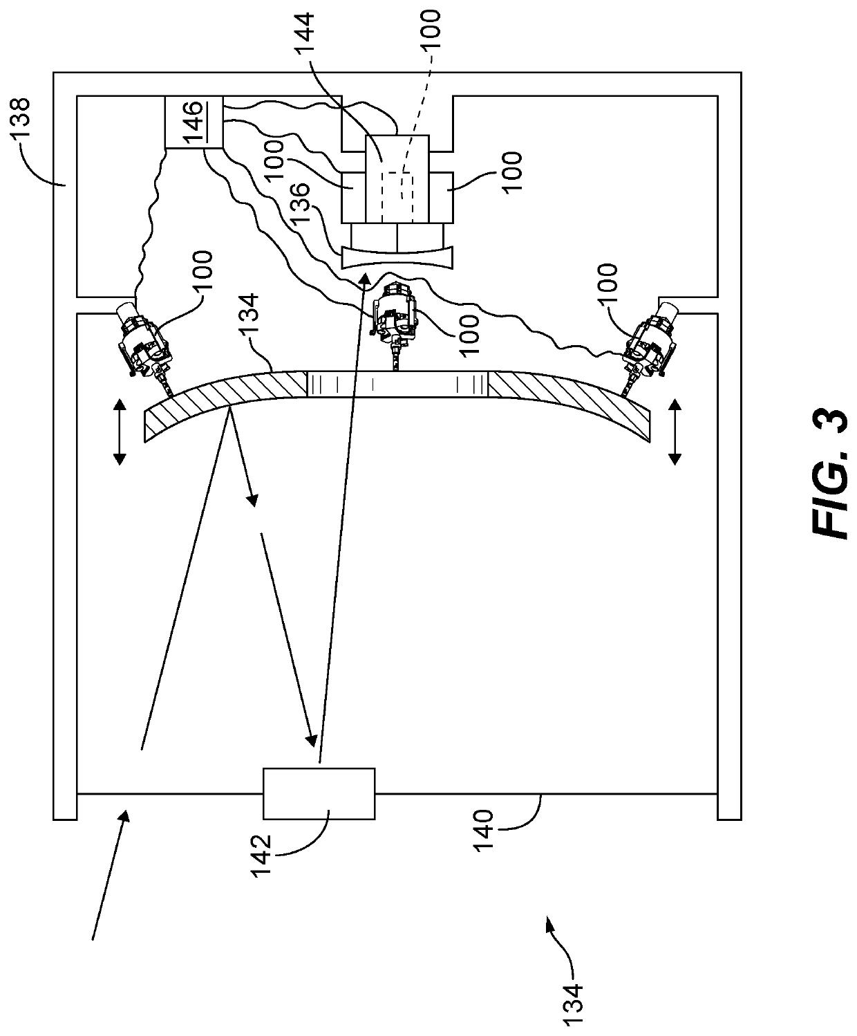
[0016]Reference will now be made to the drawings wherein like reference numerals identify similar structural features or aspects of the subject disclosure. For purposes of explanation and illustration, and not limitation, a partial view of an embodiment of an actuator system in accordance with the disclosure is shown in FIG. 1 and is designated generally by reference character 100. Other embodiments of systems in accordance with the disclosure, or aspects thereof, are provided in FIGS. 2-3, as will be described. The systems and methods described herein can be used to provide large distance actuation, e.g., on the order of millimeters, with fine distance resolution, e.g., on the order of microns or nanometers, such as for use in positioning optical elements like lenses and mirrors in optical systems.

[0017]The actuator system 100 includes a frame 102 configured to remain stationary relative to a carriage 104 within the frame 102 and connected to the frame 102 by a stacked-blade flexur...


PUM


Abstract

An actuator system includes a frame configured to remain stationary relative to a carriage within the frame and connected to the frame by a flexure assembly configured to constrain the carriage for only linear motion along an axis of the actuator system. A rotary base is configured to receive rotational input. Cross-blade flexures operatively connect the carriage to the rotary base, the cross-blade flexures including a plurality of blade flexures and being oriented at an oblique angle to the rotary base and to the axis of the actuator system. A rotary flexure operatively connects the rotary base to the frame. The cross-blade flexures and the rotary flexure are configured to convert rotary motion of the rotary base into linear motion of the carriage and to maintain axial and lateral stiffness.

Description

BACKGROUND OF THE INVENTION1. Field of the Invention[0001]Embodiments of the invention relate to actuators, and more particularly to actuators for use in converting rotational input to linear output.2. Description of Related Art[0002]In certain applications, such as optical telescopes / systems, it may be desirable to achieve precise positioning and control of various components. For example, in optical telescopes, it may be important to precisely position mirrors or optical elements over optically large distances in small increments (e.g., on the order of microns or nanometers). The need for precision, among other considerations, drives the design of actuators used in controlling and moving the optical elements. Typically, these requirements are met using a motor and screw design, with the screw being, for example, ball, roller, or lead screws. Such designs include a large number of parts, thereby adding weight and complexity to the overall system.[0003]Such conventional methods and ...

Claims


Application Information

Patent Timeline
Patent Type & Authority Patents(United States)
IPC IPC(8): F16H49/00G02B23/00F16H19/06G02B7/182
CPCF16H49/00F16H19/065F16H49/001G02B7/1827G02B23/00F16H2049/008F16H21/54
Inventor BOOKER, JESSE W.
Owner THE BF GOODRICH CO
Learn More