
Methods and apparatus for maintaining receiver operating point with changing angle-of-arrival of a received signal

a technology of receiving signal and operating point, which is applied in the direction of electrical apparatus, line-of-sight transmission, satellite communication transmission, etc., can solve the problems of increasing system size, weight, cost and complexity, and achieves less system complexity, less imparted momentum, and high tuning speed

Active Publication Date: 2022-04-12
RAYTHEON CO
View PDF55 Cites 2 Cited by
  • Summary
  • Abstract
  • Description
  • Claims
  • Application Information

AI Technical Summary

Benefits of technology

This patent is about methods and devices for keeping a laser transmitter and receiver aligned in a way that they can communicate with each other in the absence of any movement. This invention allows for faster tuning and easier alignment without the need for complicated machinery. Overall, this invention provides a simpler and more efficient way to align laser transmitters and receivers in optical communications systems.

Problems solved by technology

However, both these types of implementations require mechanical rotation in one or more planes, which can increase size, weight, cost and complexity of a system.
In addition, for these solutions, imparted momentum to the platform results, which can be problematic in some applications.

Method used


Image

  • Methods and apparatus for maintaining receiver operating point with changing angle-of-arrival of a received signal
  • Methods and apparatus for maintaining receiver operating point with changing angle-of-arrival of a received signal
  • Methods and apparatus for maintaining receiver operating point with changing angle-of-arrival of a received signal

Examples


Embodiment Construction

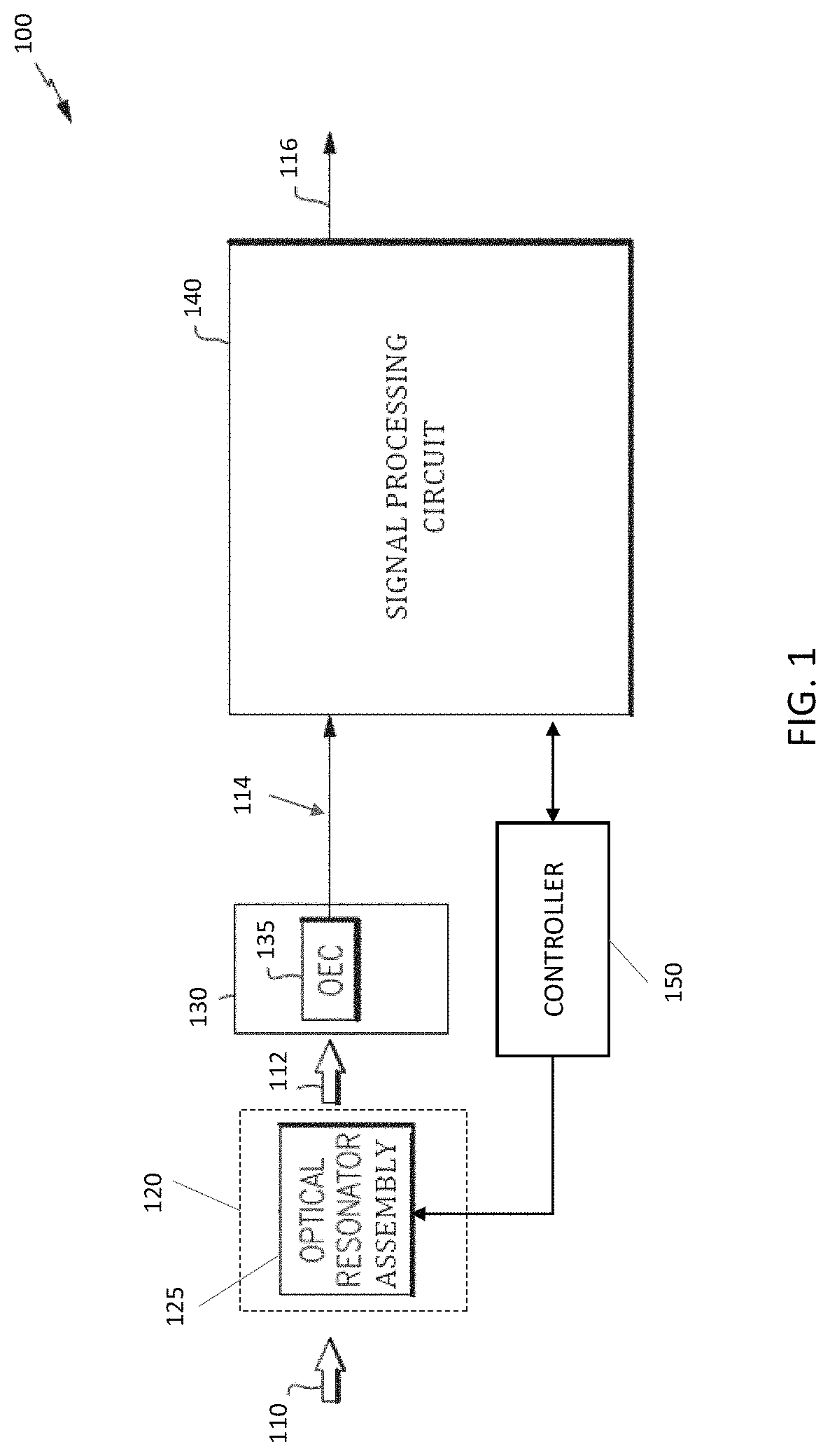
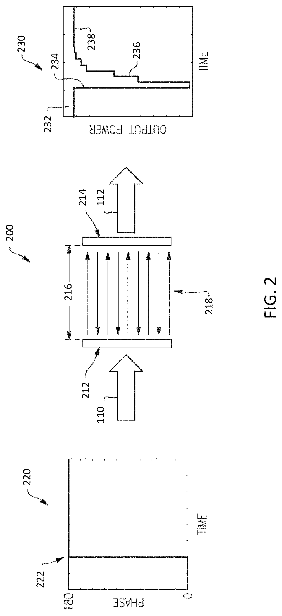
[0026]Certain optical signal receivers include an optical resonator assembly, such as a Fabry-Perot resonator assembly, a micro-ring assembly, or a non-planar resonator assembly that is used to demodulate arriving optical signals. Using an optical resonator assembly in the demodulator may offer advantages over conventional demodulation techniques, including the ability to demodulate weak optical signals without a locally coherent clock source. The arriving optical signals may be phase modulated, amplitude modulated, or frequency modulated, or may be modulated using a combination of these techniques (e.g., QAM methods). In certain examples, the optical resonator assembly converts a received a phase, amplitude, or frequency modulated optical signal into a directly detectable intensity modulated output signal, as discussed further below. The optical resonator assembly may be sensitive to the angle of arrival of the incoming optical signal, and its output response signal may change as a...


PUM


Abstract

Methods and apparatus for maintaining transmitter-receiver alignment in a free space optical communications system without substantially moving the receiver element and with very little to no imparted momentum, while also allowing for higher tuning speeds and less system complexity than conventional solutions. The methods and apparatus allow for a large field of regard at the optical receiver, without the need for electromechanical gimbals to move the entire receiver unit and without the need for steering mirrors to move and align the incoming optical beam.

Description

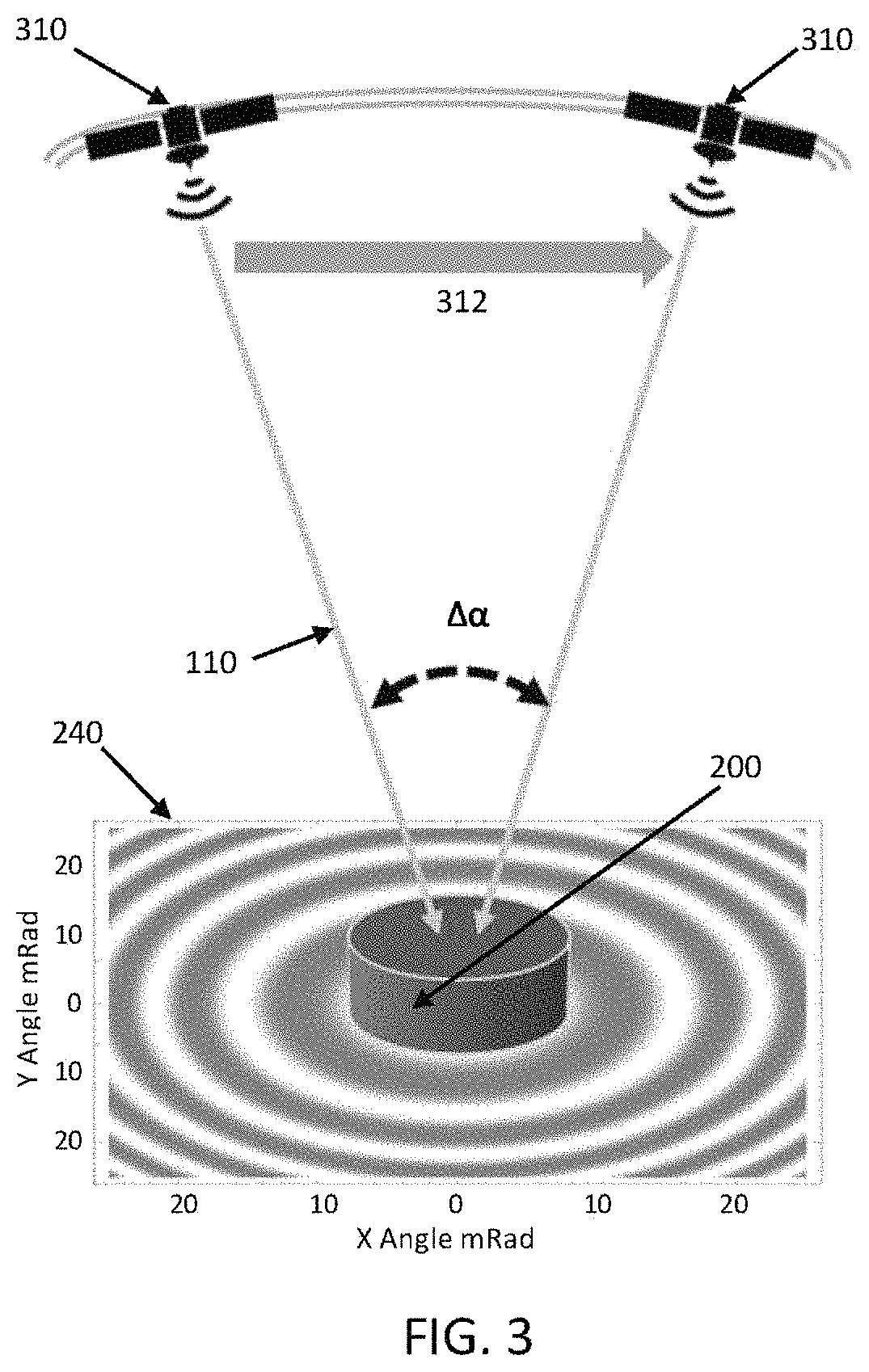
CROSS-REFERENCE TO RELATED APPLICATION[0001]This application claims priority under 35 U.S.C. § 119(e) to U.S. Provisional Application Ser. No. 62 / 835,672, titled “METHODS AND APPARATUS FOR MAINTAINING RECEIVER OPERATING POINT WITH CHANGING ANGLE-OF-ARRIVAL OF A RECEIVED SIGNAL,” filed on Apr. 18, 2019, which is hereby incorporated by reference in its entirety.BACKGROUND[0002]Many optical communication systems manipulate light waves to carry information. For instance, often a light source (e.g., a laser source) is modulated to change various properties of emitted light, such as an amplitude, phase, or frequency of the light to convey information. An optical receiver may receive an demodulate the light waves to recover the information. For free-space optical communications, there is a need to be able to receive communication signals from different angles, either because the transmitter and receiver are not completely aligned to each other, or because there is relative movement between...

Claims


Application Information

Patent Timeline
Patent Type & Authority Patents(United States)
IPC IPC(8): H04B10/00H04B10/112H04B10/54
CPCH04B10/112H04B10/54H04B10/118H04B10/672
Inventor KOWALEVICZ, ANDREWDOLGIN, BENJAMIN P.GRACEFFO, GARY M.
Owner RAYTHEON CO
Learn More