


Quick Research
Generate reliable direction feasibility study reports for your R&D in just a few steps.

Technical Q&A
Discover and master advanced knowledge NOW. Basics, ideas, possibilities, all at once.

Find Solutions
As an expert in R&D theories, this can generate solutions to your technical problems instantly.

Evaluate Feasibility
Analyze your overall solution with one click, know your potential R&D risks in advance.

Monitor Landscape
Get weekly tech updates, stay abreast of the latest tech innovations and key insights.
Foveated display system
a display system and display device technology, applied in the field of optical systems, can solve problems such as difficult design of artificial reality systems, and achieve the effect of increasing the steering range of beam-steering devices and small form factors and weigh
- Summary
- Abstract
- Description
- Claims
- Application Information
AI Technical Summary
Benefits of technology
Problems solved by technology
Method used
Image

Examples
Embodiment Construction
[0002]Embodiments of this disclosure relate generally to optical systems and, more specifically, to a foveated display system.
Description of the Related Art
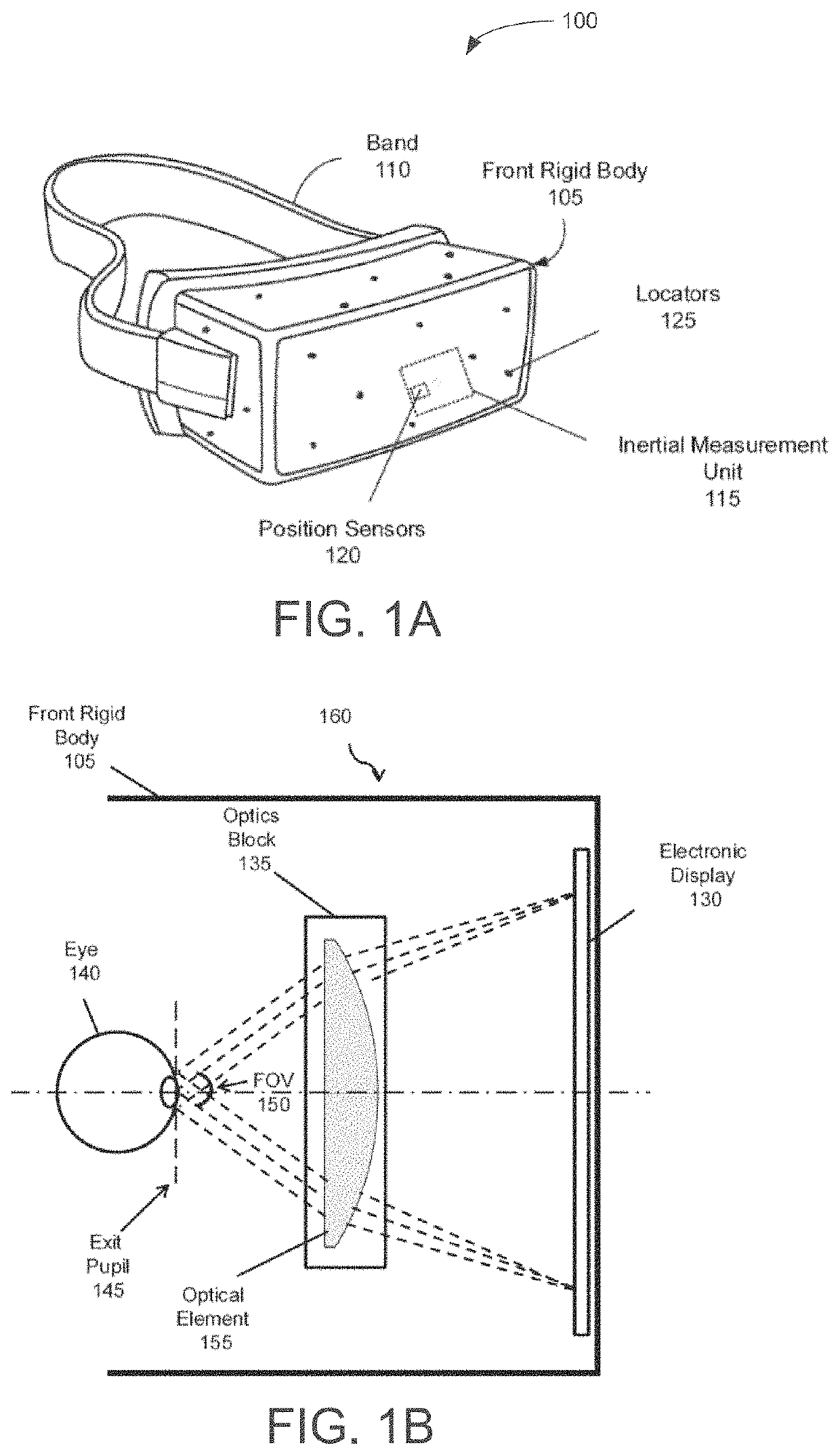
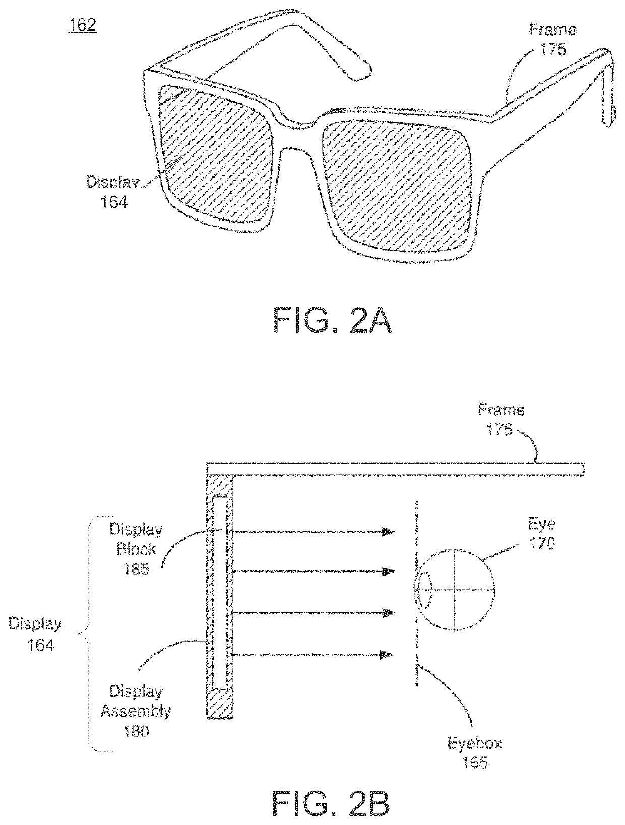
[0003]Artificial reality systems display content that may include completely generated content or generated content combined with captured (e.g., real-world) content. A realistic display should account for what a user sees in his or her peripheral vision, as well as the high-acuity vision produced by the fovea centralis (also referred to herein as the “fovea”) located in the back of the user's eyes. For some artificial reality systems, such as head-mounted display (HMD) systems, a small form factor and light design are also desirable. Designing such artificial reality systems has proven to be difficult.
SUMMARY
[0004]One embodiment of the present disclosure sets forth a foveated display system. The foveated display system includes a foveal display module comprising a lens that is angular and wavelength selective. The foveated displ...
PUM
 Abstract
Description
Claims
Application Information
 - R&D Engineer
- R&D Manager
- IP Professional
- Industry Leading Data Capabilities
- Powerful AI technology
- Patent DNA Extraction
Browse by: Latest US Patents, China's latest patents, Technical Efficacy Thesaurus, Application Domain, Technology Topic, Popular Technical Reports.
© 2024 PatSnap. All rights reserved.Legal|Privacy policy|Modern Slavery Act Transparency Statement|Sitemap|About US| Contact US: help@patsnap.com