Magnetic resonance imaging patient temperature monitoring system and related methods

a temperature monitoring system and magnetic resonance imaging technology, applied in the direction of magnetic variable regulation, instruments, applications, etc., can solve the problems of rf energy not being evenly distributed throughout the patient's body, affecting the safety of patients, so as to prevent adverse events

Active Publication Date: 2022-04-05
RTTHERMAL
View PDF39 Cites 0 Cited by
  • Summary
  • Abstract
  • Description
  • Claims
  • Application Information

AI Technical Summary

Benefits of technology

The patent is about a system and method that uses an infrared camera to monitor a patient's temperature during an MRI procedure to prevent burns on the patient's skin surface. The system can control the tilt angle of the camera and the field of view during the MRI imaging to improve the accuracy of infrared image acquisition. The camera can be positioned outside of the MRI magnetic field to minimize electromagnetic interference and noise. The camera can also be directed toward a specific hot spot on the patient's body. The system can detect an increase in skin surface temperature and subdermal temperatures and prevent RF burns while maintaining patient privacy. Overall, the system and method can help to improve safety and accuracy during MRI imaging.

Problems solved by technology

It has been discovered that RF energy absorption by the patient, implanted or nearby medical devices, and / or MRI ground loops, routinely lead to heating of the patient's skin surfaces in localized or widespread areas.
In some cases, the heating leads to RF burns on the patients.
For example, RF energy might not deposit uniformly throughout the patient's body.
In some cases, blood flow can redistribute the RF energy resulting in non-uniform, in vivo temperatures.
Certain in vivo regions can become more heated than others, and temperatures increase thereby causing RF burns.

Method used


Image

  • Magnetic resonance imaging patient temperature monitoring system and related methods
  • Magnetic resonance imaging patient temperature monitoring system and related methods
  • Magnetic resonance imaging patient temperature monitoring system and related methods

Examples


example

[0064]The current embodiments are further illustrated by the following example, which is intended to be non-limiting.

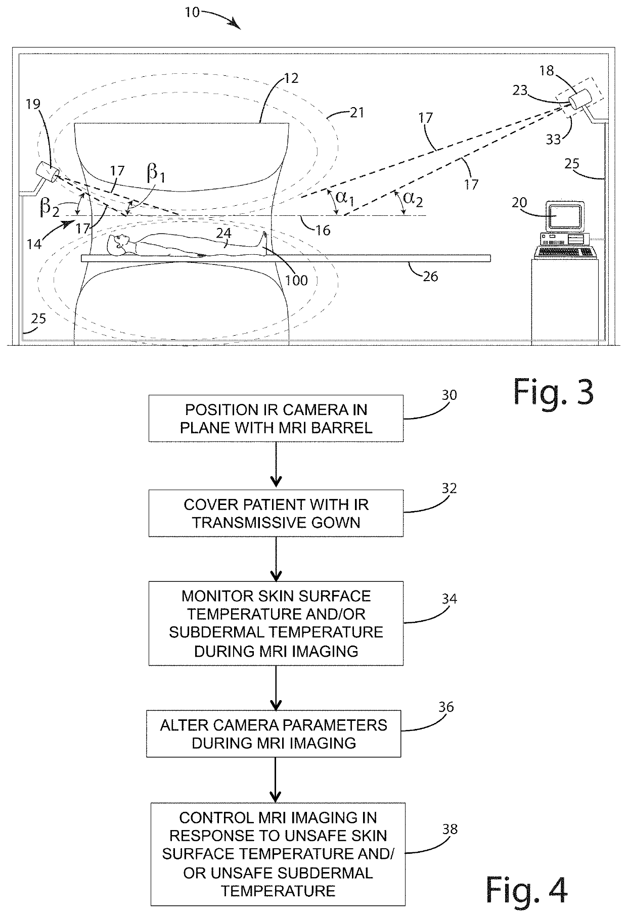
[0065]An infrared camera including a tilt lens was selected for thermal imaging of an MRI barrel. The infrared camera included the Tau 640 thermal imaging camera (from FLIR Systems, Inc.). The Tau 640 included a two-dimensional array 31 with 640×512 elements. Additional camera parameters are illustrated in FIG. 13, including a field of view of 12.4°×9.9° with a 50 mm equivalent focal length. The camera was provided with a 60 mm LWIR tilt lens 23, which is illustrated in FIG. 14, having a focal ratio of 1.2 and a focal length of 50 mm.

[0066]The infrared camera was vertically offset from the central axis of the barrel by a distance of 2.97 feet, horizontally from the head by a distance of 9.17 feet, horizontally offset from the shoulders by a distance of 10.68 feet, horizontally offset from the groin by a distance of 12.47 feet, and horizontally offset from the head by ...


PUM


Abstract

A system for monitoring a patient during MRI imaging to prevent patient burns. The system includes a barrel to provide an MRI image of a patient and an infrared camera to image the patient separately from the MRI image. The infrared camera includes an adjustable field of view and is positionable at a plurality of viewing angles relative to the longitudinal axis of the barrel. The infrared camera is coupled to a processor adapted to monitor the surface temperature of the patient based on the output of the infrared camera. The processor is further adapted to control at least one of the field of view of the infrared camera and / or the viewing angle of the camera during MRI imaging of the patient. The system further includes a patient gown formed of an infrared transmissive material that provides visual concealment for the patient.

Description

BACKGROUND OF THE INVENTION[0001]The present invention relates to magnetic resonance imaging procedures, and more particularly to systems and methods to measure and / or monitor patient temperature during such procedures to prevent burns.[0002]Magnetic residence imaging (MRI) is used to image a patient's internal organs, tissue and in some cases bone. During an MRI, radio-frequency (RF) energy is transmitted through the patient. It has been discovered that RF energy absorption by the patient, implanted or nearby medical devices, and / or MRI ground loops, routinely lead to heating of the patient's skin surfaces in localized or widespread areas. In some cases, the heating leads to RF burns on the patients. Those burns can be first, second or third degree burns in extreme cases.[0003]There are several reports indicating that the limbs or body parts of MRI burn patients were in direct contact with RF body coils or other RF transmitting coils of the MRI equipment. In other cases, it is susp...

Claims


Application Information

Patent Timeline
Patent Type & Authority Patents(United States)
IPC IPC(8): A61B5/055A61B5/00A61B5/01G01R33/28
CPCA61B5/055A61B5/0064A61B5/0077A61B5/015A61B5/445A61B5/7485G01R33/283G01R33/288
Inventor WATTS, RAYMOND C.BLACKLER, III, STEPHEN F.DEKKINGA, JACK A.KUMLER, JAMES J.
Owner RTTHERMAL
Why Eureka
Try Eureka