
Magnetorheological hydraulic damper with passive damping chamber

a technology of hydraulic dampers and dampers, applied in the direction of shock absorbers, springs/dampers, functional characteristics, etc., can solve the problems of increasing the wear and tear high cost of magnetorheological fluids, and unsatisfactory efficiency of mechanical valve assemblies, etc., to achieve cost-effective and simple manufacturing

Active Publication Date: 2022-03-22
BEIJING WEST IND CO LTD
View PDF19 Cites 1 Cited by
  • Summary
  • Abstract
  • Description
  • Claims
  • Application Information

AI Technical Summary

Benefits of technology

Enables cost-effective, adaptable damping characteristics by combining the benefits of both fluid types, allowing for responsive damping control with reduced wear and tear and simpler control systems, improving efficiency and adaptability to road conditions.

Problems solved by technology

Magnetorheological fluids, however, are costly and the magnetic particles suspended within the carrier fluid greatly increase the wear and tear of the mechanical valve assemblies of the damper.
Furthermore, relatively complex control systems equipped with numerous sensors are required to continuously control magnetorheological dampers, while their efficiency often remains unsatisfactory.

Method used


Image

  • Magnetorheological hydraulic damper with passive damping chamber
  • Magnetorheological hydraulic damper with passive damping chamber
  • Magnetorheological hydraulic damper with passive damping chamber

Examples


Embodiment Construction

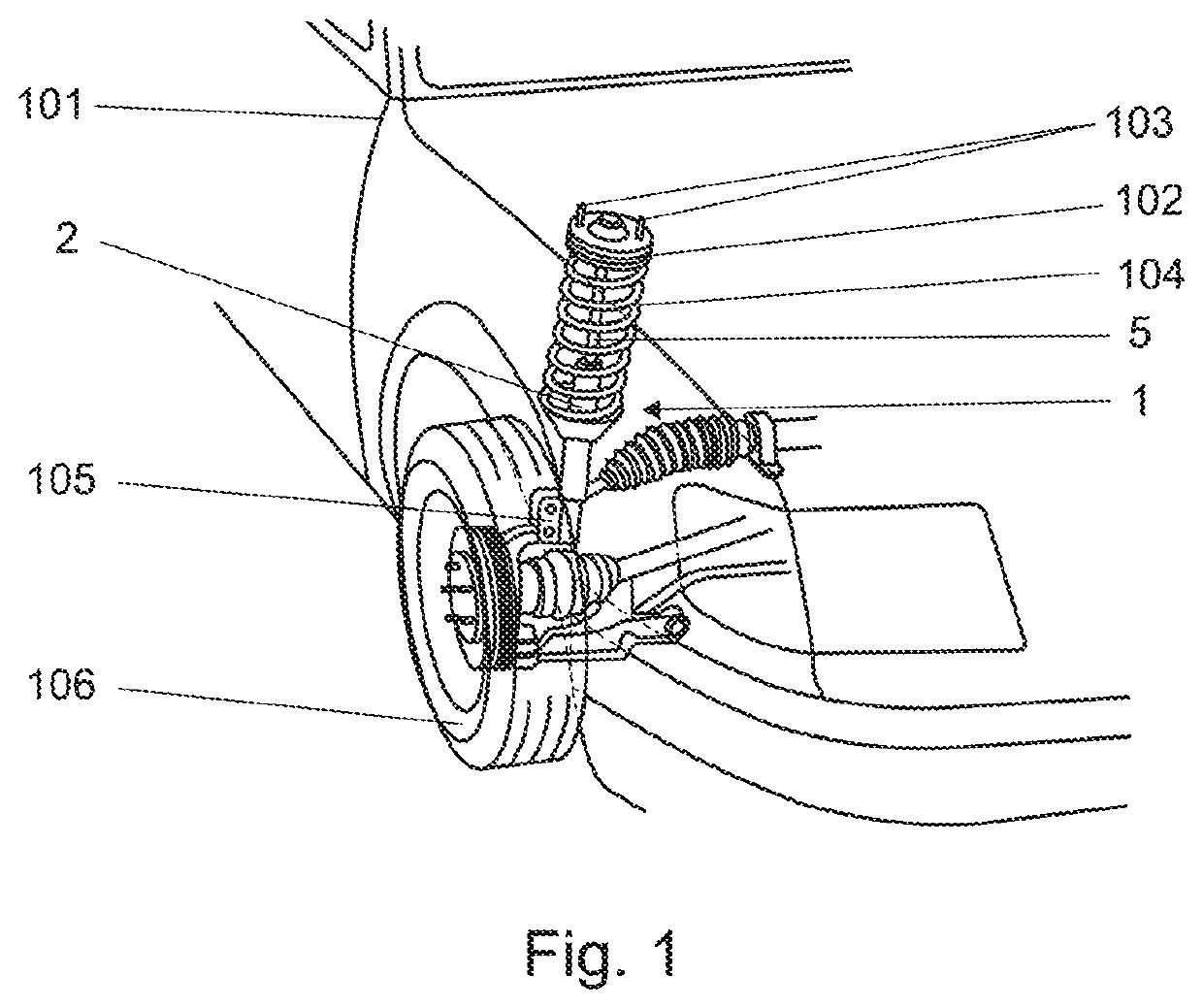
[0018]Referring to the Figures, wherein like numerals indicate corresponding parts throughout the several views, FIG. 1 illustrates a damper assembly 1 constructed in accordance with an embodiment of the present invention coupled to a vehicle chassis 101. The damper assembly 1 can be coupled to the vehicle chassis 101 using a top mount 102 and a plurality of screws 103 wherein the plurality of screws 103 are disposed along a periphery of an upper surface of the top mount 102. The top mount 102 couples to a coil spring 104 and a piston rod 5 of the damper 1. An external tube 2 of the damper assembly 1 can be coupled to a steering knuckle 105 supporting the vehicle wheel 106.

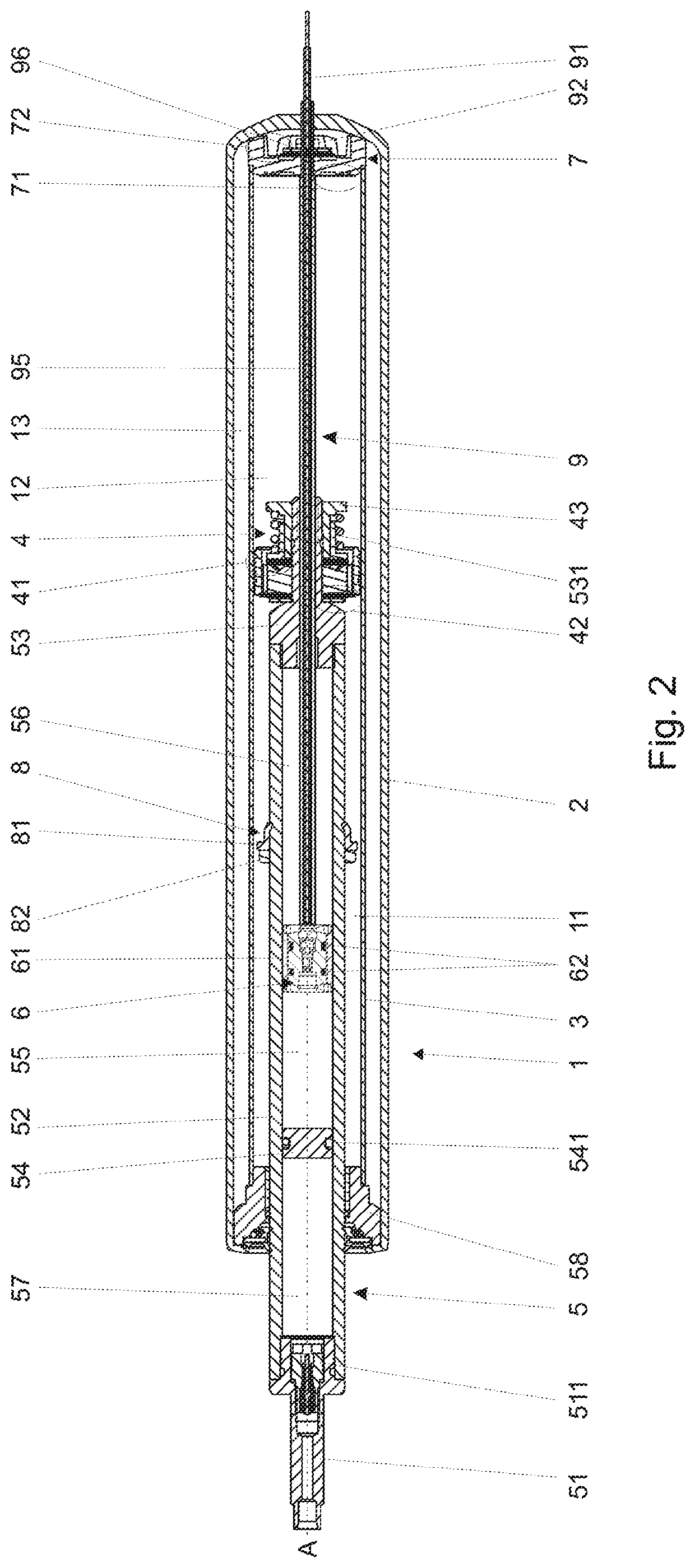
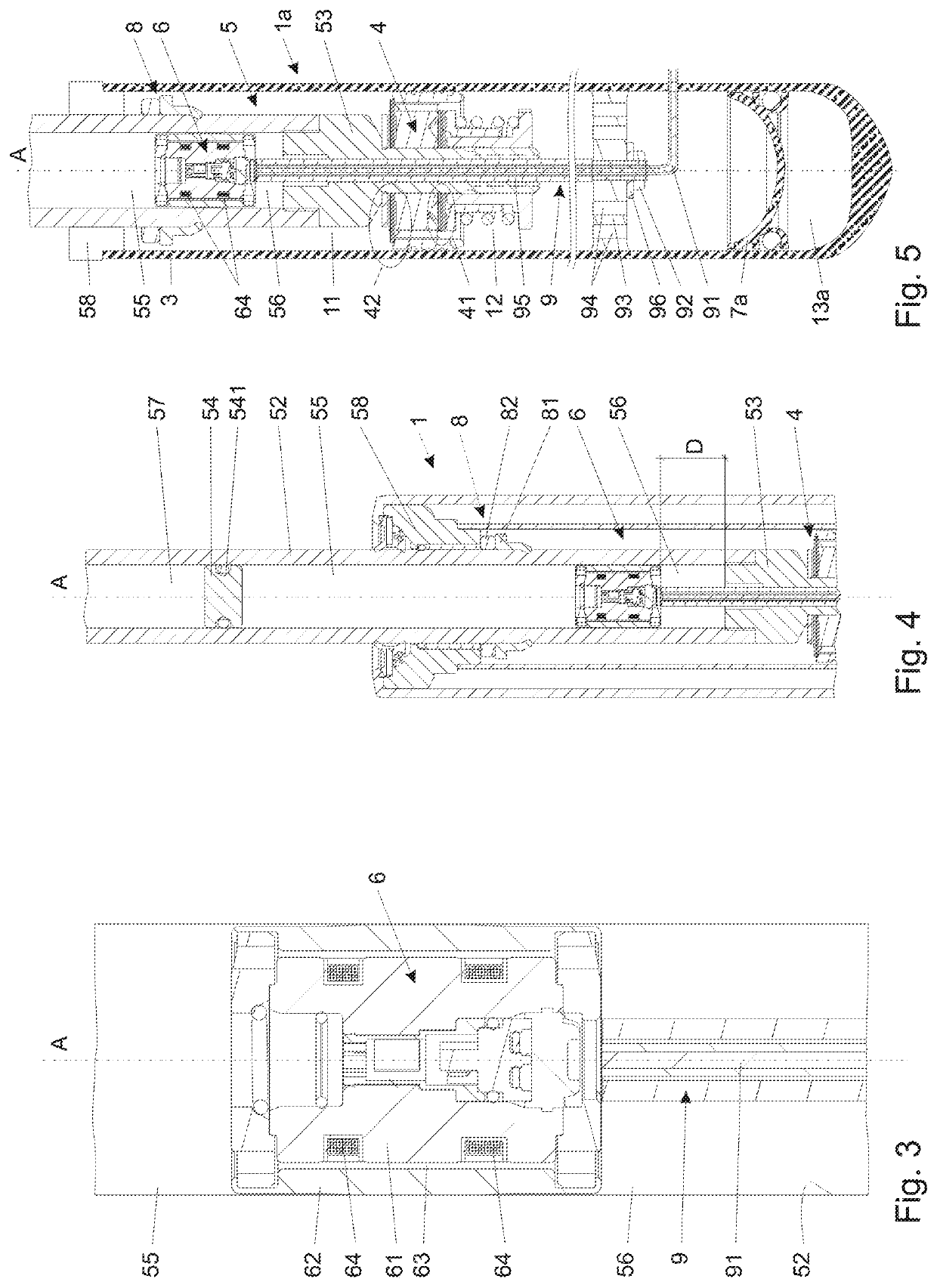
[0019]FIG. 2 illustrates a twin-tube damper 1, also referred to as a damper assembly 1, constructed in accordance with an embodiment of the present invention. The damper assembly 1 comprises an external tube 2 and a main tube 3. The main tube 3 extends along a center axis A and defines a fluid chamber 11, 12 for c...


PUM


Abstract

A damper assembly comprises a main tube extending along a center axis defining a fluid chamber. A main piston is located in the main tube dividing the fluid chamber into a compression chamber and a rebound chamber. A piston rod extends into the main tube and coupled to the main piston. The piston rod defines an annular chamber extending along the center axis. A slidable partition is located in the annular chamber dividing the annular chamber into a magnetorheological chamber and a compensation chamber. A secondary piston is slidably disposed in the magnetorheological chamber dividing the magnetorheological chamber into a magnetorheological compression chamber and a magnetorheological rebound chamber. A secondary piston rod sealingly and slidably guided through the main piston and couples to the main tube for moving the secondary piston axially in the magnetorheological chamber.

Description

CROSS REFERENCE TO RELATED APPLICATION[0001]The present application claims priority Chinese Patent Application Ser. No. CN201910710312.4, filed on Aug. 2, 2019, the entire disclosure of which is hereby incorporated herein by reference in its entirety.BACKGROUND OF THE INVENTION1. Field of the Invention[0002]The present invention relates generally to a damper assembly and in particular, a damper assembly for a vehicle.2. Description of the Prior Art[0003]Passive dampers employing working fluid featuring constant viscosity are known to provide versatile design parameters that may be used to provide any desired characteristic of the damping force, shaped not only with respect to the velocity of the piston rod, but also with respect to high frequency and / or low amplitude events. Nonetheless the damping characteristic of passive dampers integrated into a suspension system of a motor vehicle is fixed and irresponsive to particular and ever changing road conditions that can be detected by ...

Claims


Application Information

Patent Timeline
Patent Type & Authority Patents(United States)
IPC IPC(8): F16F9/53F16F9/06F16F9/32F16F9/34F16F9/43F16F9/58B60G13/08B60G17/08
CPCF16F9/535F16F9/062F16F9/063F16F9/065F16F9/067F16F9/3221F16F9/34F16F9/43F16F9/585B60G13/08B60G17/08B60G2202/24B60G2204/45B60G2206/41B60G2500/10B60G2600/182B60G2800/162F16F2222/12F16F2224/045F16F2228/066F16F2228/12F16F2232/08F16F2234/02F16F9/18F16F9/3207F16F9/182
Inventor KNAPCZYK, II, MARCIN
Owner BEIJING WEST IND CO LTD
Learn More