
Knee joint structure

a knee joint and joint technology, applied in knee joints, prostheses, medical science, etc., can solve the problems of inconvenient adjustment of the strength of the elastic body, and achieve the effects of enhancing the safety of operation, reducing the drawback of a prior art knee joint, and reducing the effor

Active Publication Date: 2022-03-22
KEN DALL ENTERPRISE
View PDF3 Cites 0 Cited by
  • Summary
  • Abstract
  • Description
  • Claims
  • Application Information

AI Technical Summary

Benefits of technology

Enhances walking safety by maintaining a stable gait and allows for easy adjustment of elastic strength according to walking speed, preventing continuous bending and tipping.

Problems solved by technology

Further, due to the structural arrangement that the position-returning device 921 is arranged on the knee-joint body portion 92 and the protrusion block 931 is arranged on the connection rod 93, together with the knee joint body portion 92 being connected to a shank prosthesis, adjustment of the strength of the elastic body can only be carried out by first removing the shank prosthesis, and this causes inconvenience in adjusting the strength of the elastic body.

Method used


Image

  • Knee joint structure
  • Knee joint structure
  • Knee joint structure

Examples


Embodiment Construction

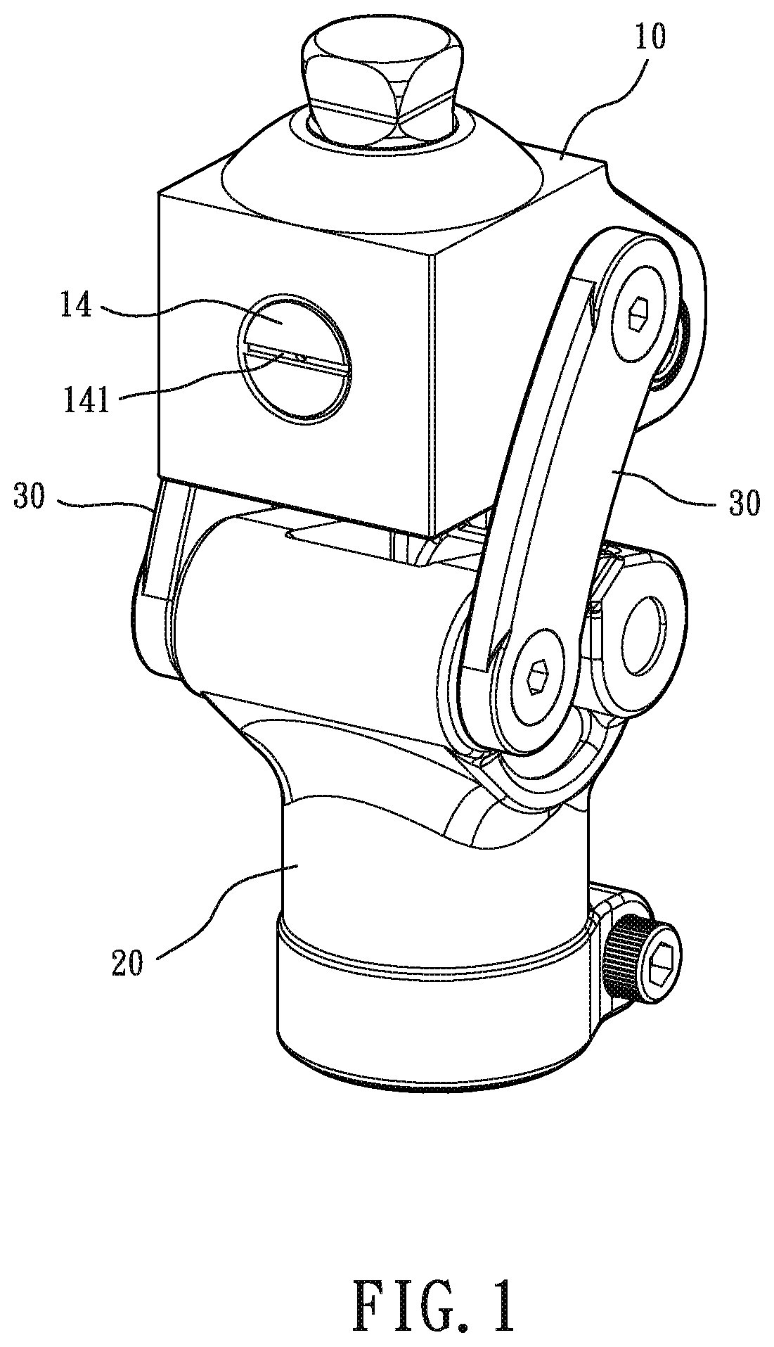
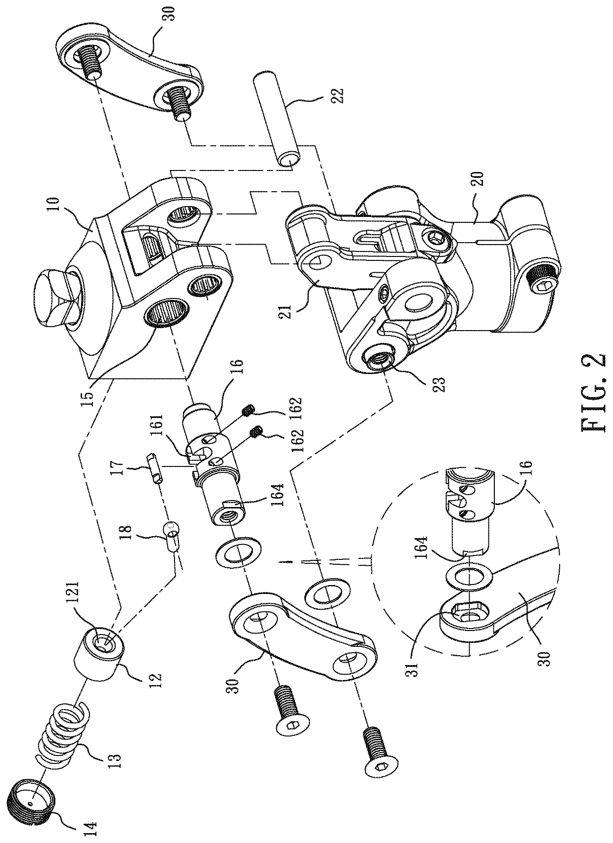
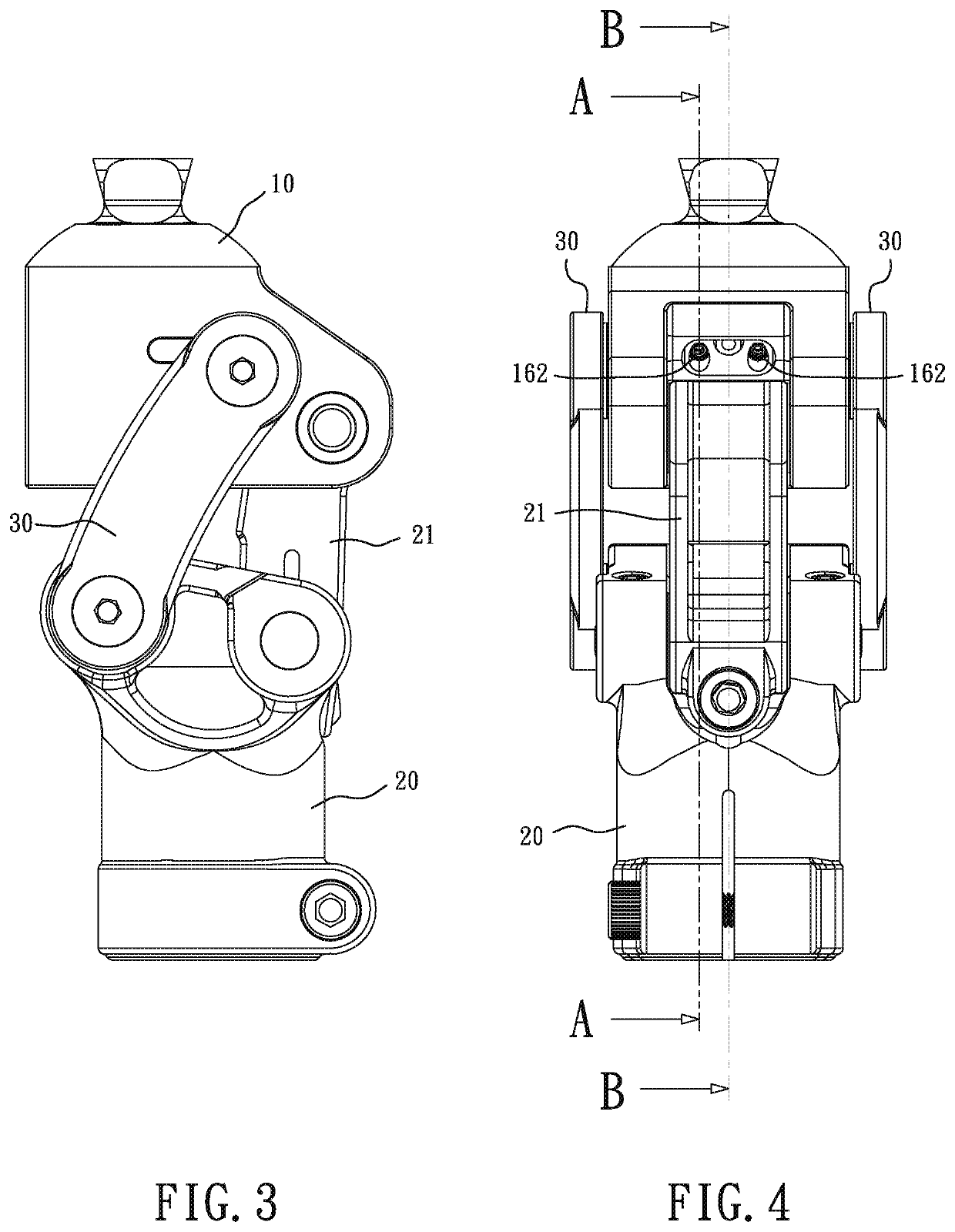
[0025]Referring to FIGS. 1-6, the present invention comprises a knee-joint head portion 10, a knee-joint body portion 20, and two curved plates 30. A detailed description will be provided below:

[0026]The knee joint head portion 10 is formed with a position-returning bore 11. Arranged inside the position-returning bore 11 include a piston 12, an elastic body 13, and an adjustment cap 14. The elastic body 13 has two opposite ends respectively supported on the piston 12 and the adjustment cap 14. The knee joint head portion 10 is formed with an axle hole 15. The axle hole 15 receives a transmission axle 16 arranged therein. The transmission axle 16 is formed with a notch 161, and a push-bar axle 17 is arranged in the notch 161. The push-bar axle 17 pivotally couples a push bar 18 that is operable to push, drive, and move the piston 12.

[0027]The knee-joint body portion 20 includes a connection rod 21. The connection rod 21 has an end that is pivotally connected, by a first shaft 22, to ...


PUM


Abstract

A knee joint structure includes a knee joint head portion, a knee-joint body portion, and at least one curved plate. The knee joint head portion includes a position-returning device made up of a piston, an elastic body, and an adjustment cap and a transmission axle. The transmission axle includes a push-bar axle, which is pivotally coupled to a push bar operable to drive and move the piston. The knee-joint body portion includes a connection rod pivotally connected to the knee joint head portion. The curved plate connects the transmission axle and the knee joint body portion.

Description

TECHNICAL FIELD OF THE INVENTION[0001]The present invention relates to a knee joint structure, and more particularly to a knee joint structure of a prosthetic limb user that enhances walking safety, eases adjustment of joint restoration strength, and helps save effort required for walking.DESCRIPTION OF THE PRIOR ART[0002]A prosthetic limb is an artificially made limb that functionally replaces a damaged limb or aesthetically repairs the outside appearing of the damaged limb. Among others, a knee joint is a key feature of the prosthetic limb, because it is concerned with gait and dynamic balance of walking in order to take the place of a natural knee joint in respect of the functions of supporting and walking.[0003]A prior art knee joint structure, as shown in FIGS. 15 and 16, generally comprises a knee joint head portion 91, a knee-joint body portion 92, and a connection rod 93 and curved plates 94 that connect the knee-joint head portion 91 and the knee-joint body portion 92 toget...

Claims


Application Information

Patent Timeline
Patent Type & Authority Patents(United States)
IPC IPC(8): A61F2/38A61F2/30A61F2/46
CPCA61F2/38A61F2002/3007A61F2002/30329A61F2002/30535A61F2002/30624A61F2002/4688A61F2/644A61F2002/503A61F2002/5073
Inventor CHENG, CHIA-PAOLIANG, CHIH-HSUANWU, HSIANG-MING
Owner KEN DALL ENTERPRISE
Learn More